
Power module and current converter

A power module and power unit technology, applied in the field of electronics, can solve the problems of high height, large height and volume, and high converter height, and achieve the effect of avoiding large overall volume, small height and volume, and improving convenience.

Active Publication Date: 2013-05-01
CHINA CNR CORPORATION
View PDF6 Cites 23 Cited by
  • Summary
  • Abstract
  • Description
  • Claims
  • Application Information

AI Technical Summary

Problems solved by technology

In the prior art, in order to achieve effective heat dissipation, the power module usually adopts a water-cooled structure. The power module of this structure can cool the IGBT through water cooling. However, in the power module of this structure, it needs to be separately installed for cooling. Additional components such as water pipes and water pumps make the height and volume of the power module larger, which cannot be suitable for occasions that require a higher volume; components, which will make the height and volume of each power module too large when assembled in the box of the converter
In addition, in the prior art, there are also power modules adopting a traveling air-cooled structure. This kind of power module also has the problem of high height, and the power module is installed separately, which leads to the problem that the overall volume of the converter is too large.
[0004] To sum up, in the existing power modules with water-cooled structure or running air-cooled structure, the height and volume of the converter using this type of power module are high, and it is not suitable for converters that require smaller height and volume. middle

Method used


Image

  • Power module and current converter
  • Power module and current converter
  • Power module and current converter

Examples


Embodiment Construction

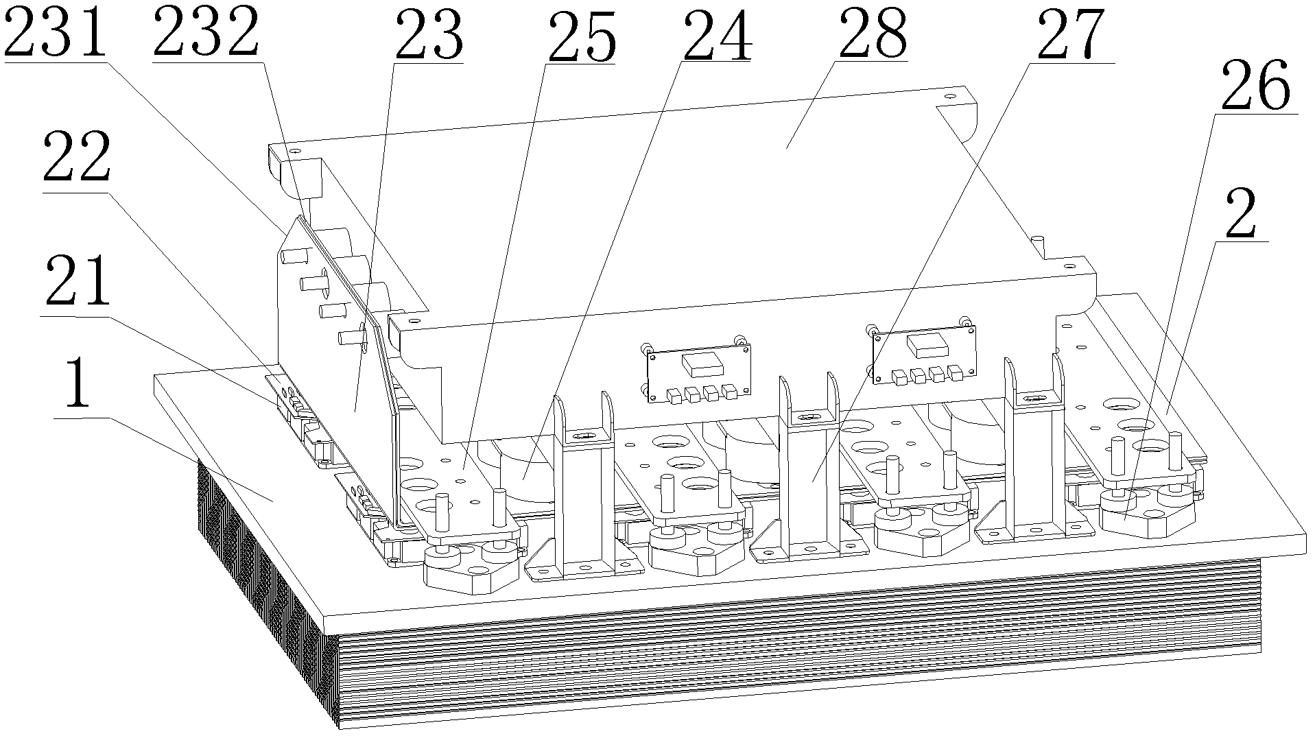
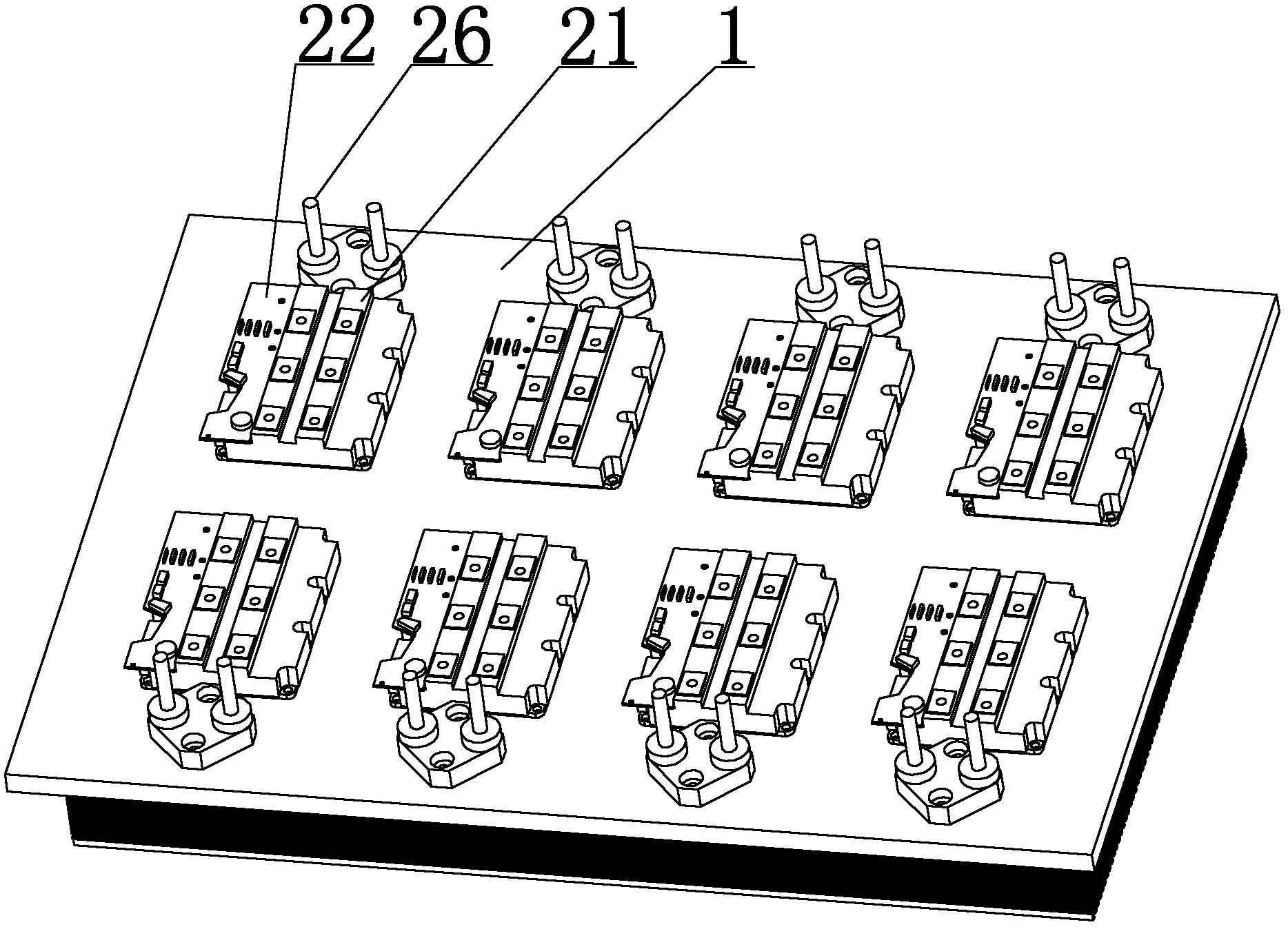
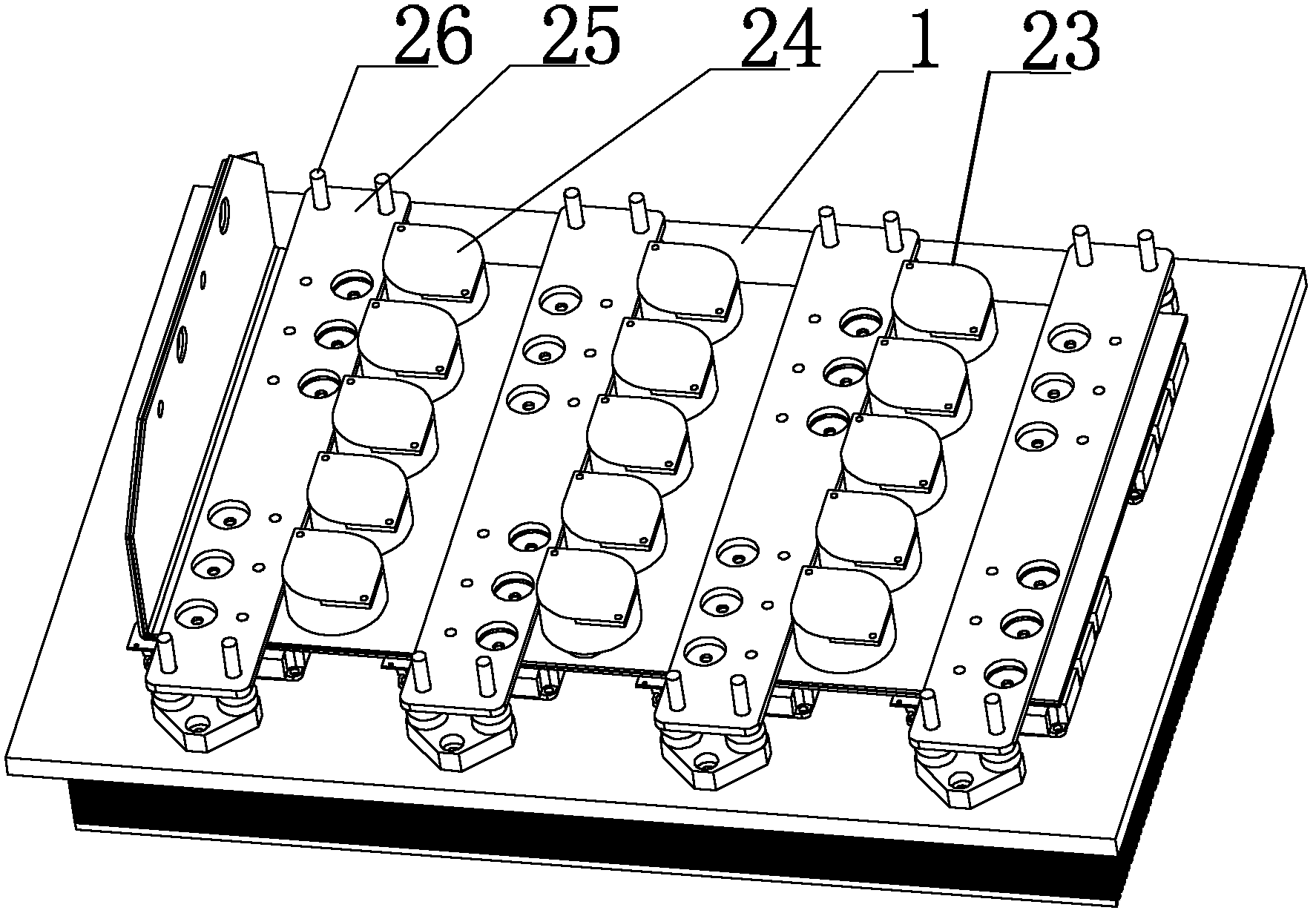
[0028] figure 1 A schematic structural diagram of a power module provided by an embodiment of the present invention. Such as figure 1 As shown, the power module of this embodiment includes a flat radiator 1, on which there are multiple groups of power units 2, and each power unit 2 includes an IGBT 21, a drive circuit board 22, a composite busbar 23, a surge Capacitor 24 and AC outlet copper bar 25. Among them, the IGBT 21 is directly installed on the surface of the flat radiator 1, the driving circuit board 22 is installed on the IGBT 21, and is electrically connected with the IGBT 21; the composite busbar 23 is installed on the IGBT 21 and the driving circuit board 22, and the composite busbar 23 includes a DC positive copper bar 231 and a DC negative copper bar 232. The DC negative copper bar 232 and the DC positive copper bar 231 are electrically connected to the IGBT 21 respectively; The DC negative copper bar 231 and the DC positive copper bar 232 are electrically con...


PUM


Abstract

The invention discloses a power module and a current converter. The power module comprises a flat plate type radiator on which a plurality of groups of power units are arranged side by side, each power unit comprises an IGBT (Insulated Gate Bipolar Transistor), a driving circuit board, complex busbars, a surge capacitor and an alternating outgoing line copper bar, wherein the IGBT is arranged on the surface of the flat plate type radiator; the driving circuit board is arranged on the IGBT and electrically connected with the IGBT; the complex busbars are arranged on the IGBT and the driving circuit board and consist of a direct current positive copper bar and a direct current negative copper bar which are respectively connected with the IGBT electrically; the surge capacitor is arranged on the complex busbars and electrically connected with the direct current positive copper bar and the direct current negative copper bar on the complex busbars; the alternating current outgoing line copper bar is arranged on the complex busbars and connected with the IGBT electrically; the complex busbars in all power units have an integrated structure. According to the technical scheme, the power module and the current converter are simple in structure, and convenient to realize, and the size of the power module can be effectively reduced.

Description

technical field [0001] The invention relates to electronic technology, in particular to a power module and a converter. Background technique [0002] The power of the traction converter in the subway vehicle is large, and its order of magnitude can reach 1MW. Among them, as the core component of the converter, the components in the power module are relatively large in size and have a large heat dissipation power. With the development of technology, the requirements for the size of the power module are getting higher and higher. Therefore, it is very important to effectively reduce the size of the power module while ensuring the electrical performance of the power module. [0003] Among them, the power module is a power component with an insulated gate bipolar transistor (Insulated Gate Bipolar Transistor, IGBT) as the core, and is used as a power component of an inverter or a chopper in a converter, which mainly includes: a converter The main functional component in an inve...

Claims


Application Information

Patent Timeline
IPC IPC(8): H02M1/00H05K7/20
Inventor 张可飞
Owner CHINA CNR CORPORATION
Learn More