
Rotary transformer system and control method thereof

A technology of resolver and control method, which is applied in the field of resolver, can solve problems such as expensive chips, and achieve the effect of simple operation

Inactive Publication Date: 2013-05-01
TIANJIN QINGYUAN ELECTRIC VEHICLE
View PDF5 Cites 16 Cited by
  • Summary
  • Abstract
  • Description
  • Claims
  • Application Information

AI Technical Summary

Problems solved by technology

However, these chips are expensive due to their specific performance and special purposes.

Method used


Image

  • Rotary transformer system and control method thereof
  • Rotary transformer system and control method thereof
  • Rotary transformer system and control method thereof

Examples


Embodiment Construction

[0028] In order to make the purpose, technical solution and advantages of the present invention clearer, the implementation manners of the present invention will be further described in detail below.

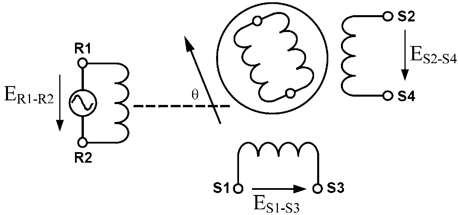
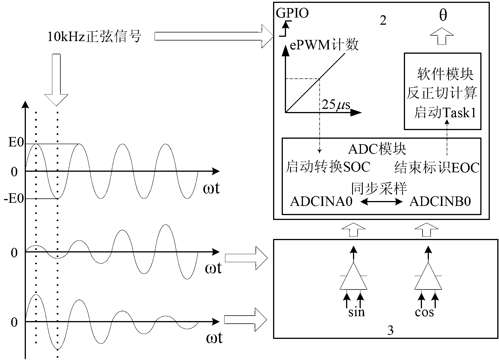
[0029] see figure 1 , figure 2 and image 3 , a rotary transformer system comprising: a rotary transformer 1, a digital signal control chip (DSC) 2 and a signal conditioning circuit 3;

[0030] The digital signal control chip 2 modulates and outputs a sinusoidal excitation signal with a preset frequency, which is used as the rated voltage of the resolver 1 after conditioning; the zero-crossing moment of the sinusoidal excitation signal is used as the interrupt signal of the digital signal control chip 2; the timer of the digital signal control chip 2 Start counting with the zero-crossing moment as the time reference, and after a delay of 1 / 4 cycle, the digital signal control chip 2 collects the AD sampling of the sine and cosine signals of the resolver 1;

[0031] The resolv...


PUM


Abstract

The invention discloses a rotary transformer system and a control method thereof. A digital signal control chip modulates and outputs a sinusoidal excitation signal with preset frequency, the sinusoidal excitation signal is used as rated voltage of a rotary transformer after being conditioned; a zero passage moment of the sinusoidal excitation signal is used as an interrupt signal of the digital signal control chip; a timer of the digital signal control chip starts to count by taking the zero passage moment as a time reference, the digital signal control chip collects an AD sample of a sine and cosine signal of the rotary transformer after 1 / 4 period is delayed; the rotary transformer outputs two sine and cosine modulation and simulation signals; a signal conditioning circuit is used for conditioning the two sine and cosine modulation and simulation signals to obtain the conditioned simulation signals to be transmitted to the digital signal control chip; and the digital signal control chip synchronously samples the conditioned simulation signals to obtain an AD conversion result and output a rotor position angle value. According to the method, a special calculating chip is removed, so that the integration level of a control system is improved, and the cost of the control system is reduced.

Description

technical field [0001] The present invention relates to a rotary transformer, in particular to a rotary transformer system and a control method thereof. Background technique [0002] A resolver is a position sensor based on the principle of electromagnetic coupling, which is essentially a small AC motor used for angle measurement. The resolver requires an external excitation signal as an input signal, and its output is two orthogonal analog signals. Therefore, the digital signal of the corresponding position must be obtained through analog-to-digital conversion and calculation before it can be input to the control chip. [0003] At present, some dedicated digital conversion (RDC) chips such as AD2S1200 of AD Company or AU6802 of TAMAGAWA Company can complete the generation of resolver excitation signal and the conversion of output signal to digital position signal. But these chips are expensive due to their specific performance and special purpose. Contents of the inventi...

Claims


Application Information

Patent Timeline
IPC IPC(8): H02P6/16H01F38/18
Inventor 黄雷苟毅彤
Owner TIANJIN QINGYUAN ELECTRIC VEHICLE
Learn More