Fracture of tibial plateau internal fixing device

A fixation device, tibial plateau technology, applied in the direction of internal fixator, fixator, internal bone synthesis, etc., can solve the problems of inability to quantify fracture fragment pressure, screw plastic deformation, inability to quantify torque, etc., to prevent initial fixation failure, increase The effect of pressure strength, fixed protection and improved stability

Inactive Publication Date: 2013-05-08
无锡世一电力机械设备有限公司
View PDF0 Cites 3 Cited by
  • Summary
  • Abstract
  • Description
  • Claims
  • Application Information

AI Technical Summary

Problems solved by technology

The biomechanical principle of this treatment method and the internal fixation used is as follows: the lag screw relies on the axial compressive stress between the spacer or the bone plate and the cortical bone to form a compression effect between the fracture fragments to realize the reduction and restoration of the fracture fragments. Pressurize and firmly fix; however, at present, when the lag screw achieves reduction, pressurization and firm fixation between the fracture fragments, the torque required to screw in the lag screw cannot be quantified, and the pressure between the fracture fragments cannot be quantified, and there is no biological fixation effect. The problem with the initial fixed failure
[0003] The so-called initial fixation failure refers to: the torque required for the lag screw screwed into the fracture fragment depends on the experience of the surgeon, and it is usually overtightened, resulting in plastic deformation of the screw, fracture or damage to the interface between the bone and the thread, making the internal fixation invalid
The torque required to screw the lag screw into the fracture depends on the experience of the operator, and the accumulation of experience depends on the experience of failure. There is a slope of the learning curve, which is not conducive to the formation of quantitative standards for this technique.

Method used


Image

  • Fracture of tibial plateau internal fixing device
  • Fracture of tibial plateau internal fixing device

Examples


Embodiment Construction

[0013] The present invention will be described in further detail below in conjunction with the accompanying drawings.

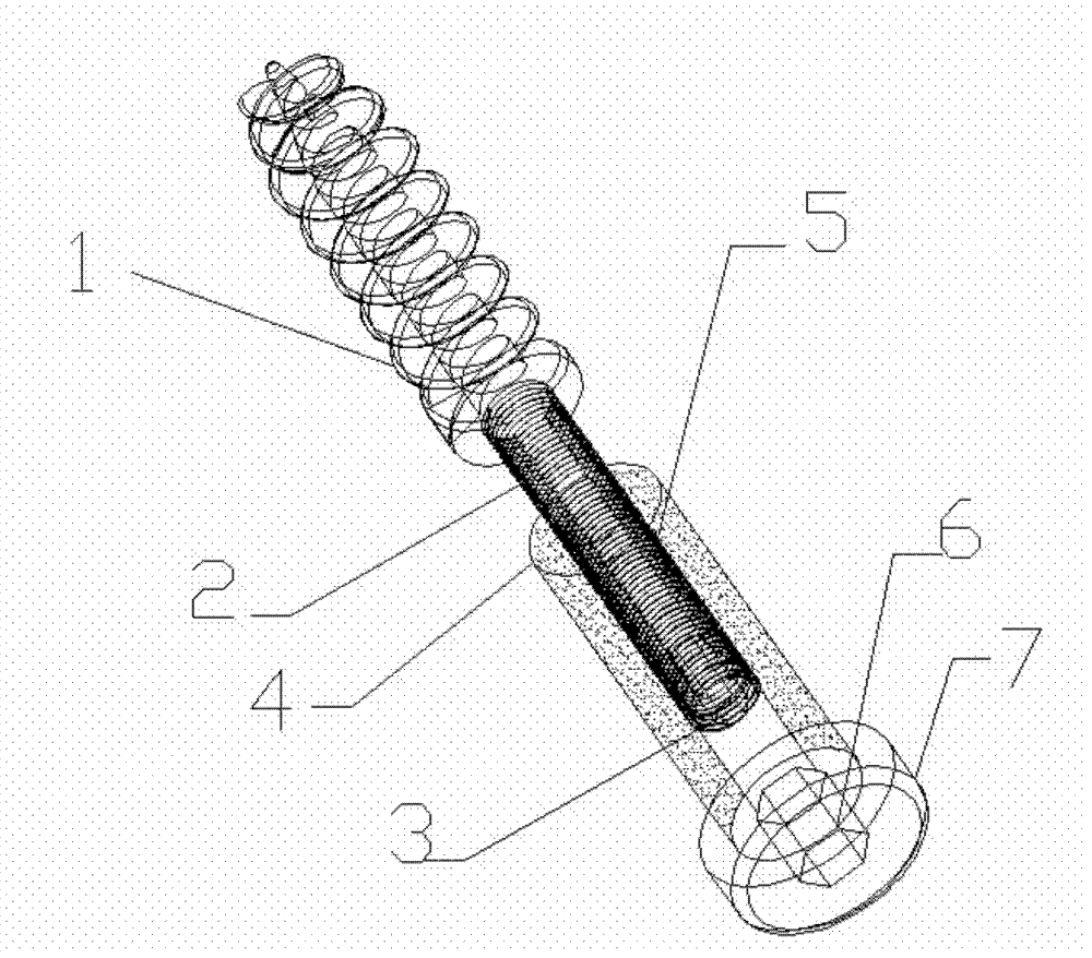
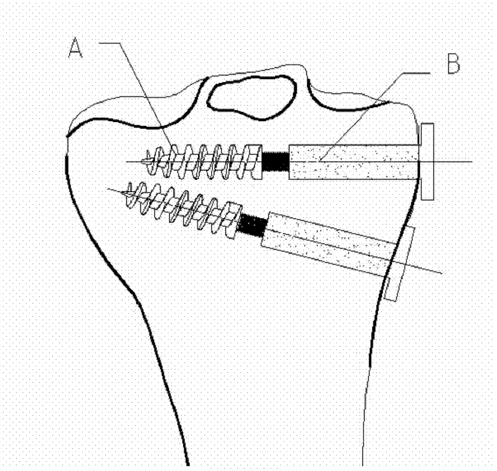
[0014] like figure 1 , figure 2 The internal fixation device for tibial plateau fractures described in the present invention is divided into two parts: component A and component B. Component A consists of thread 1 and thread 2, and the tail is a hollow prism structure, such as a hexagonal prism or other shapes, located in the core of thread 2. One end of the component B is provided with a thread 5 to match the thread 2 of the component A. The thread 5 is a part for realizing the compression effect between the fracture fragments. The other end of the component B is provided with a terminal 7, which contains a prismatic hole 6, and the prismatic hole 6 is connected to the The thread 5 communicates through the transition portion 3 . The surface of component B is treated with sandblasting, porous and hydroxyapatite coating to form a microporous layer surface ...


PUM


Abstract

The invention discloses a fracture of tibial plateau internal fixing device which consists of a component (A) and a component (B). The component (A) consists of two sections of main screw threads. The fracture of tibial plateau internal fixing device is characterized in that the front end screw thread (1) is a taper screw thread. The thread pitch of the screw thread (1) is larger than that of a screw thread (2). The thread depth of the screw thread (1) is deeper than that of the screw thread (2). The rear end screw thread (2) is connected with the front end internal thread of the component (B) in a cooperation mode. The component (B) is an internal hollow cylindrical body. A tail end (7) is arranged on the tail of the component (B). A tightening structure (6) which matches with an outer sleeve of compound sleeves is arranged at the tail end (7). The tightening structure (6) communicates with the internal hollow portion of the component (B). According to bone mineral density of patient, pressure required by intra- articular fracture bone and torque required by tightening device is quantified so as to be beneficial to early recovery of patient.

Description

technical field [0001] The invention relates to a medical fracture fixation device, in particular to an internal fixation system applied to tibial plateau fractures. Background technique [0002] In the treatment of tibial plateau fractures that require surgery, it is necessary to use lag screws to achieve reduction, compression and strong fixation between the fracture fragments. The biomechanical principle of this treatment method and the internal fixation used is as follows: the lag screw relies on the axial compressive stress between the spacer or the bone plate and the cortical bone to form a compression effect between the fracture fragments to realize the reduction and restoration of the fracture fragments. Pressurize and firmly fix; however, at present, when the lag screw achieves reduction, pressurization and firm fixation between the fracture fragments, the torque required to screw in the lag screw cannot be quantified, and the pressure between the fracture fragments...

Claims


Application Information

Patent Timeline
Patent Type & Authority Applications(China)
IPC IPC(8): A61B17/68A61B17/86
Inventor 徐达强王鹏潘金祥
Owner 无锡世一电力机械设备有限公司
Why Eureka
Try Eureka