
Milling system for lathe

A milling and lathe technology, applied in the field of machine tool equipment, can solve problems such as inconvenient use, and achieve the effect of convenient use, simple structure, and expanded functions

Active Publication Date: 2015-06-03
TIANSHUI SPARK MACHINE TOOL
View PDF5 Cites 0 Cited by
  • Summary
  • Abstract
  • Description
  • Claims
  • Application Information

AI Technical Summary

Problems solved by technology

[0003] The object of the present invention is to avoid the disadvantages of inconvenient use in the prior art and provide a milling system for lathes, which adds a set of mechanisms for realizing the milling function on the existing ordinary lathes, thereby effectively solving the defects in the prior art

Method used


Image

  • Milling system for lathe
  • Milling system for lathe

Examples


Embodiment Construction

[0012] The principles and features of the present invention are described below in conjunction with the accompanying drawings, and the examples given are only used to explain the present invention, and are not intended to limit the scope of the present invention.

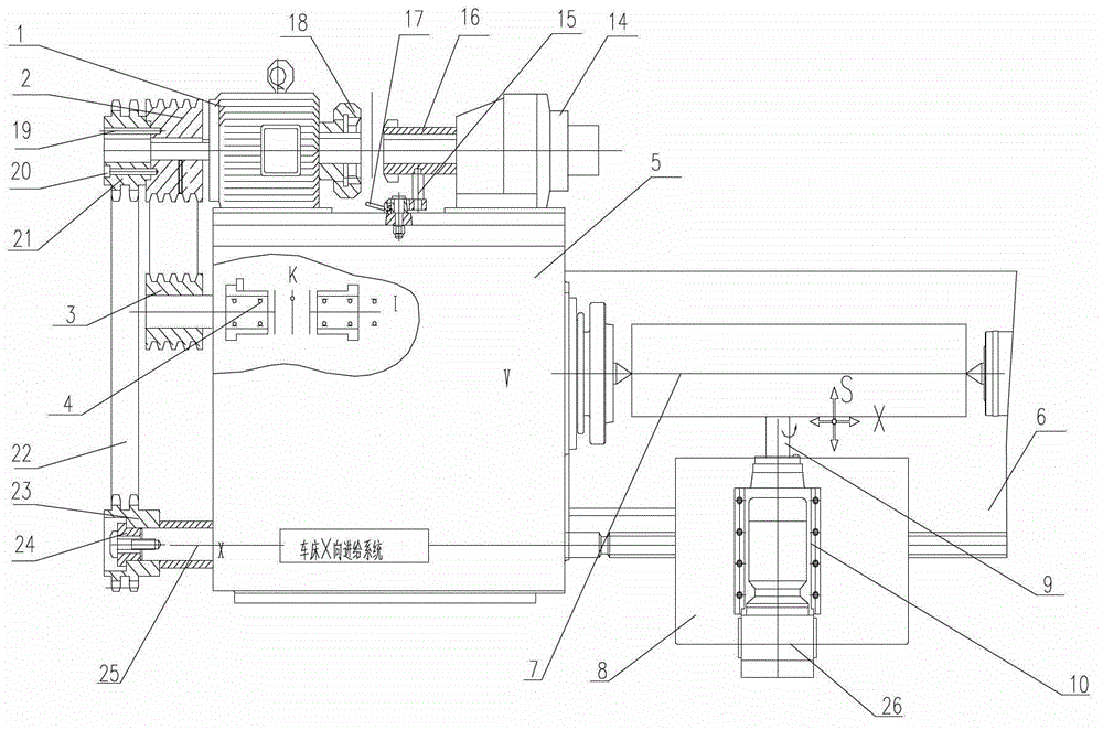
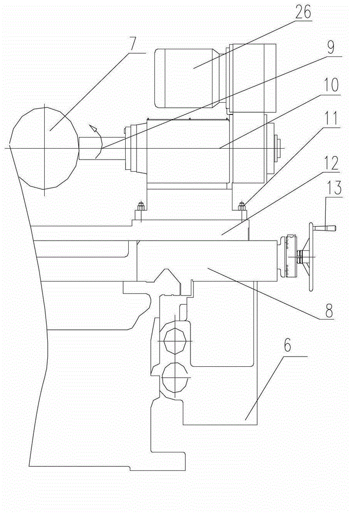
[0013] Such as figure 1 and 2 As shown, the described milling system for a lathe includes a bed 6 and a headstock headstock 5, the headstock headstock 5 is provided with a main motor 1, and the main motor 1 passes through the driving pulley 2 on the power output shaft. The driven pulley 3 is connected with the friction clutch 4 in the headstock 5, and the carriage 8 on the bed 6 is connected with the X-direction feed system in the headstock 5. The milling drive motor 14 on the box 5 and the milling tool mechanism 10 arranged on the carriage 8, the power output shaft of the milling drive motor 14 is provided with an internal gear 18 meshing with the main motor power output shaft rear end. The sliding gear 16 and th...


PUM


Abstract

The invention relates to the technical field of lathe equipment, especially relates a milling system for a lathe. The milling system comprises a lathe body and a lathe head spindle box, wherein the milling system further comprises a milling driving motor arranged on the lathe head spindle box, and a milling cutter mechanism arranged on a carriage; a slipping gear meshed with an inner gear at the rear end of a main motor power shaft is arranged on a power output shaft of the milling driving motor; a driving chain wheel is fixedly arranged at the external side of a driving belt pulley and is connected with a driven chain wheel by a chain; and the driven chain wheel is connected with an X-direction feeding system in the lathe head spindle box to drive the carriage. By additionally arranging a transmission mechanism and a milling cutter mechanism which can be used for realizing a milling function on the basis of the existing normal lathes and by using the external wheel chain mechanism for driving, the milling system for the lathe, disclosed by the invention, is capable of normally realizing the functions of original lathe, realizing the key slot milling on a key slot-carrying shaft and greatly saving the processing cost of shaft-type parts provided with key slots, and is simple in structure and convenient to use.

Description

technical field [0001] The invention relates to the technical field of machine tools, in particular to a milling system for lathes. Background technique [0002] At present, the shaft parts in mechanical equipment are generally processed by ordinary lathes. Most of the shaft parts in the prior art are provided with key grooves on the outer surface. When processing such parts, the method often used is to first The outer circle is processed on an ordinary lathe, and then a keyway milling machine is used to mill the keyway. This process generally requires two machine tools and two positioning and clamping to complete the processing of the part. Its disadvantages are large equipment investment, complicated processing steps, inconvenient use, and high processing cost. Contents of the invention [0003] The object of the present invention is to avoid the disadvantages of inconvenient use in the prior art and provide a milling system for lathes, which adds a set of mechanisms fo...

Claims


Application Information

Patent Timeline
Patent Type & Authority Patents(China)
IPC IPC(8): B23C7/02
Inventor 刘克林李海珍
Owner TIANSHUI SPARK MACHINE TOOL
Learn More