Control method of new energy automobile in motor-stalling working condition

A new energy vehicle, motor stall technology, applied in the direction of motor, electric vehicle, control drive, etc., can solve the problem of cost increase

Active Publication Date: 2013-05-08
UNITED AUTOMOTIVE ELECTRONICS SYST
View PDF5 Cites 20 Cited by
  • Summary
  • Abstract
  • Description
  • Claims
  • Application Information

AI Technical Summary

Problems solved by technology

[0009] Aiming at motor stalling conditions, the current common practice is to increase the output torque of the permanent magnet synchronous motor 30 by increasing the current conduction capability of the power switching device, which will lead to a large increase in cost

Method used


Image

  • Control method of new energy automobile in motor-stalling working condition
  • Control method of new energy automobile in motor-stalling working condition
  • Control method of new energy automobile in motor-stalling working condition

Examples


Embodiment Construction

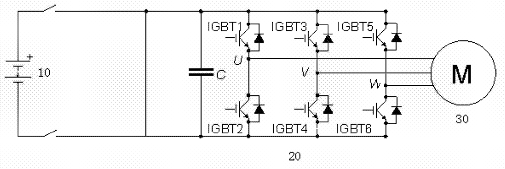
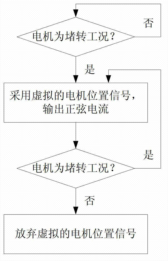
[0020] see figure 2 , the control method of the new energy vehicle in this application under the motor locked-rotor condition is: once the motor controller judges that the permanent magnet synchronous motor is in the locked-rotor condition, the virtual motor position signal is used as the input of the motor controller, so that The motor controller outputs sinusoidal current to the permanent magnet synchronous motor. Until the motor controller judges that the permanent magnet synchronous motor is no longer in a locked-rotor condition, the virtual motor position signal is given up as the input of the motor controller.

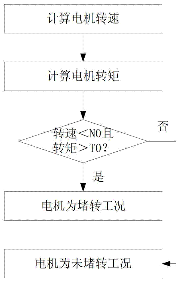
[0021] see image 3 , which is the method for the motor controller to judge whether the permanent magnet synchronous motor is in a locked-rotor condition. It includes the following steps:

[0022] In the first step, the motor controller collects the position sensor signal of the permanent magnet synchronous motor to obtain the current speed of the permanent m...


PUM


Abstract

The invention discloses a control method of a new energy automobile in a motor-stalling working condition. Once a motor controller judges the fact that a permanent magnet synchronous motor works in the motor-stalling working condition, virtual motor position signals serve as input of the motor controller, and therefore, the motor controller outputs sinusoidal current to the permanent magnet synchronous motor. The fact that the virtual motor position signals serve as the input of the motor controller is stopped until the motor controller judges the fact that the permanent magnet synchronous motor does not work in the motor-stalling working condition. According to the control method, output torque of the permanent magnet synchronous motor in the motor-stalling working condition achieves or approaches the maximal torque in the non-motor-stalling working condition, therefore short large-torque requirements on the condition that an automobile starts on a slope or driving wheels are blocked by barriers are met, resistance is overcome by the automobile, and the permanent magnet synchronous motor can break away from the motor-stalling working condition.

Description

technical field [0001] The present application relates to a motor control method of a new energy vehicle (a pure electric vehicle, or a pure electric drive mode in a hybrid vehicle), in particular to a control method under a motor stall condition. Background technique [0002] see figure 1 , which is a motor drive system in a new energy vehicle, including a high-voltage battery 10 , a motor controller 20 and a permanent magnet synchronous motor 30 . [0003] The high-voltage battery 10 outputs high-voltage direct current to the motor controller 20 to provide energy. The high-voltage battery 10 can also obtain an input high-voltage direct current from the motor controller 20 for charging. [0004] The DC terminal of the motor controller 20 is connected to the high-voltage battery 10, and the AC terminal is connected to the three-phase AC port of the permanent magnet synchronous motor 30 to drive the permanent magnet synchronous motor 30 to output torque and power, and to co...

Claims


Application Information

Patent Timeline
Patent Type & Authority Applications(China)
IPC IPC(8): B60L15/20
CPCY02T10/644Y02T10/64Y02T10/72
Inventor 毕路高智孔勇进何海
Owner UNITED AUTOMOTIVE ELECTRONICS SYST
Why Eureka
Try Eureka