Pendulum cylinder pneumatic engine

A pneumatic engine and cylinder technology, applied in the direction of machines/engines, mechanical equipment, etc., can solve the problems of internal combustion engines such as small stroke-to-bore ratio, small crankshaft turning radius, poor stiffness and strength, etc., and achieve the effect of increasing turning radius

Inactive Publication Date: 2019-10-22
广州永恒新能源科技有限公司
View PDF4 Cites 0 Cited by
  • Summary
  • Abstract
  • Description
  • Claims
  • Application Information

AI Technical Summary

Problems solved by technology

The advantages of this cylinder block are small body height, light weight, compact structure, easy processing, and easy disassembly and assembly of the crankshaft; but its disadvantages are poor rigidity and strength.
[0004] The traditional internal combustion engine crankcase is limited by its structure, so that the cylinder and the crankcase are relatively static. The upper crankcase and the cylinder block are cast as one, and the lower crankcase is used to store lubricating oil and seal the upper crankcase, so it is also called It is an oil pan diagram, the cylinder and the crankcase are fixed, resulting in a small radius of gyration of the crankshaft, which in turn makes the stroke-to-bore ratio of the internal combustion engine also small, which cannot meet the power output of the engine with high torque

Method used


Image

  • Pendulum cylinder pneumatic engine
  • Pendulum cylinder pneumatic engine

Examples


Embodiment Construction

[0016] The following will clearly and completely describe the technical solutions in the embodiments of the present invention with reference to the accompanying drawings in the embodiments of the present invention. Obviously, the described embodiments are only some, not all, embodiments of the present invention. Based on the embodiments of the present invention, all other embodiments obtained by persons of ordinary skill in the art without making creative efforts belong to the protection scope of the present invention.

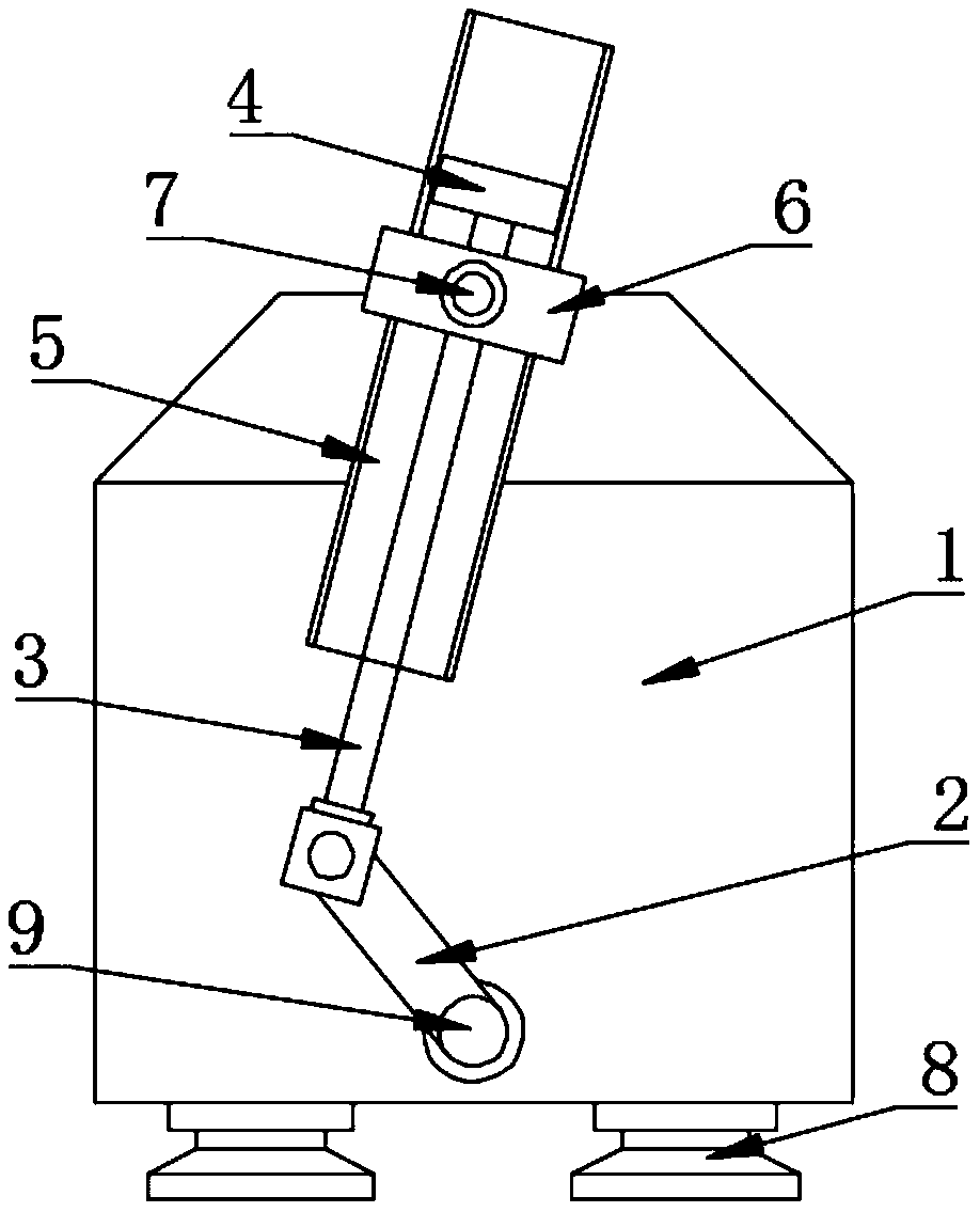
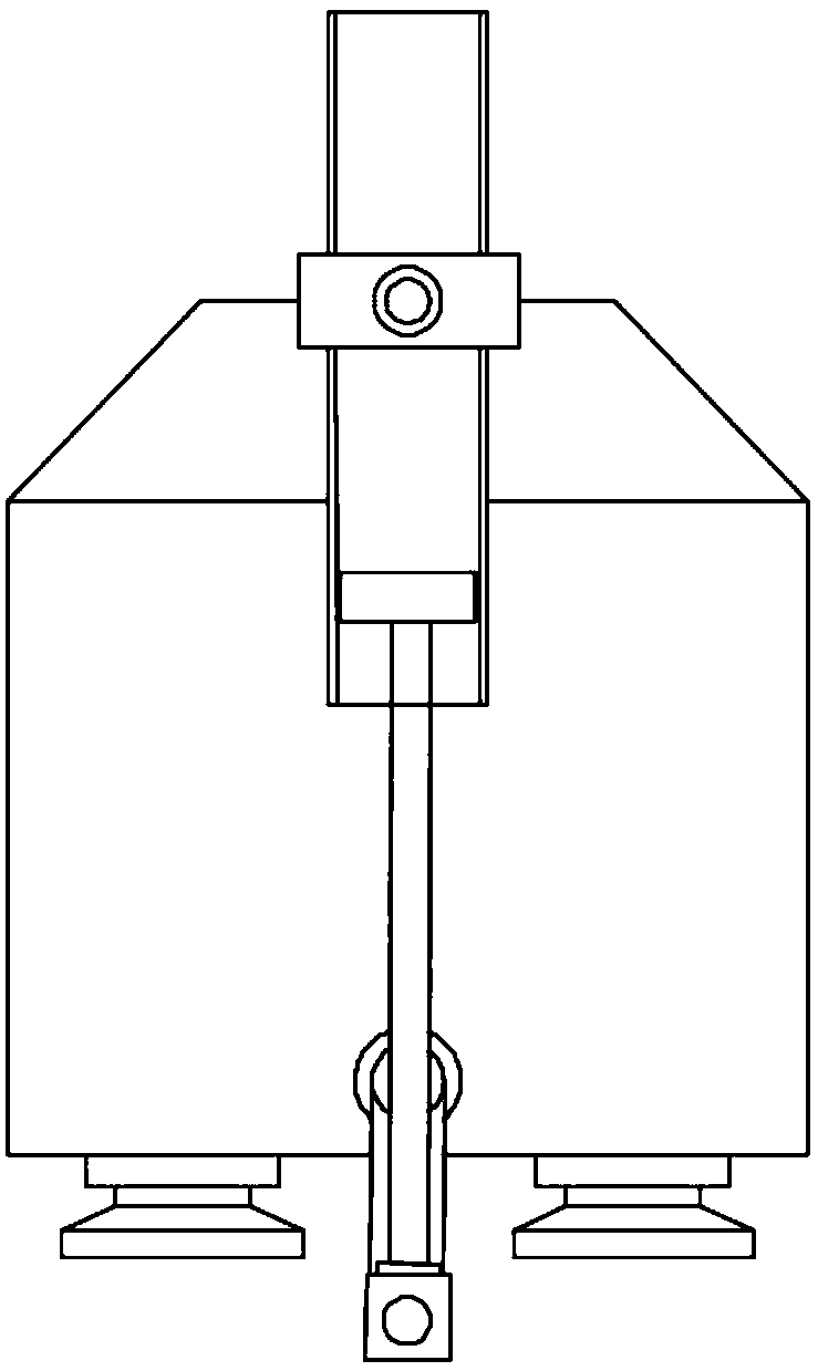
[0017] see Figure 1~2 , in an embodiment of the present invention, a pendulum cylinder pneumatic engine includes a crankcase 1, a movable rod 3, a cylinder 5, a connecting shaft 7 and a driving shaft 9; the lower center of the crankcase 1 is provided with a driving shaft 9, and the driving shaft 9 Connect the inner ring of the bearing, the outer ring of the bearing is fixedly connected to the bearing seat, the bearing seat is fixedly connected to the crankcas...


PUM


Abstract

The invention discloses a pendulum cylinder pneumatic engine. The end of a driving shaft is fixedly connected with a crankshaft, and the crankshaft is rotationally connected with the lower end of a movable rod. The upper portion of the movable rod is sleeved with the lower portion of a cylinder. The upper end of the movable rod is fixedly connected with a piston block. The edge of the piston blockis in sliding connection with the inner wall of the cylinder in a sealed manner, and the middle of the cylinder is sleeved with a lantern ring. The middle of the lantern ring is fixedly connected with the end of a connecting shaft. The other end of the connecting shaft is connected with another bearing inner race. A bearing outer race is fixedly connected with another bearing pedestal. The bearing pedestal is fixedly connected with the center of the upper portion of a crankcase. The engine breaks through structural characteristics of traditional internal combustion engines, the cylinder fixedto the crankcase is separated, all cylinders can become components which can oscillate left and right along with corresponding connecting rods, through such changes, the stroke-bore ratio (S / D) of the internal combustion engine is directly increased by several times or even more from 0.8-1.2, thus, the turning radius of the crankshaft can be increased by several times or even more, and the requirement for the large torque of the engine is met.

Description

technical field [0001] The invention relates to a power device, in particular to a pendulous cylinder pneumatic engine. Background technique [0002] An engine is a machine that can convert other forms of energy into mechanical energy, including internal combustion engines (gasoline engines, etc.), external combustion engines (Stirling engines, steam engines, etc.), electric motors, etc. For example, internal combustion engines usually convert chemical energy into mechanical energy. The engine is not only applicable to the power generation device, but also refers to the whole machine including the power device (such as: gasoline engine, aero engine). [0003] The cylinder block and the upper crankcase of the water-cooled engine are often cast into one body, which is called the cylinder block-the crankcase, which can also be called the cylinder block. The cylinder block is generally made of gray cast iron. The cylindrical cavity on the upper part of the cylinder block is ca...

Claims


Application Information

Patent Timeline
Patent Type & Authority Applications(China)
IPC IPC(8): F02B75/32
CPCF02B75/32
Inventor 胡学文
Owner 广州永恒新能源科技有限公司
Why Eureka
Try Eureka