A Multi-motor Flexible Torque Concentrated Drive Combination Box and Electric Vehicle
A centralized drive and multi-motor technology, which is applied in the field of vehicles, can solve the problems of vehicles not being able to drive normally, the weight of the electric drive system, and insufficient power performance, so as to improve driving comfort, reduce shifting frustration, and improve efficiency.
- Summary
- Abstract
- Description
- Claims
- Application Information
AI Technical Summary
Problems solved by technology
Method used
Image
Examples
Embodiment 1
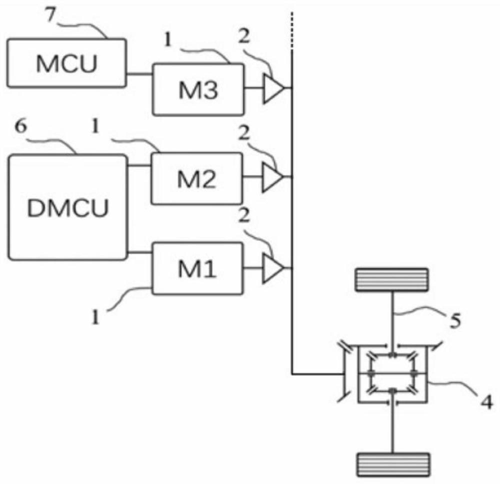
[0047] refer to Figure 1 to Figure 3 As shown, the multi-motor flexible torque centralized drive combination box of this embodiment may at least include a power source 1 and a reduction gear assembly 2 . Further, the multi-motor flexible torque centralized drive combination box may also include a differential 4 .
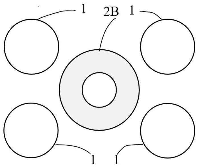
[0048] The number of power sources 1 is at least two, and each power source 1 includes a driving motor 1A for outputting driving force. The performance and geometric dimensions of each driving motor 1A are the same to simplify the control of driving motor 1A. It should be noted, Figure 1 to Figure 3 The number of power sources 1 shown in the figure is only illustrative, and can be selected according to vehicle application requirements in practical applications, for example, it can be 2, 3, or even more. In a specific embodiment, the number of power sources 1 may be four. The reduction gear assembly 2 has the same number as the power source 1, and is connected ...
Embodiment 2
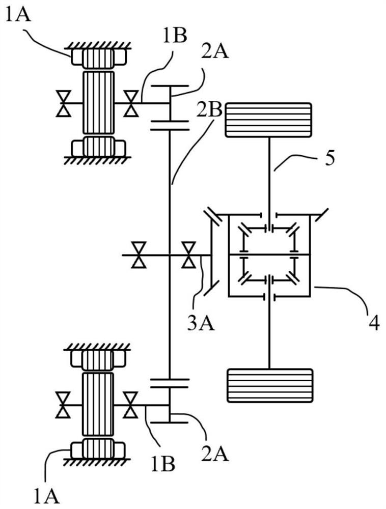
[0056] refer to Figure 4 and Figure 5 As shown, the difference between Embodiment 2 and Embodiment 1 is that the multi-motor flexible torque centralized drive combination box of this embodiment also includes a speed change device connected between the input end of the differential 4 and the output end of each reduction gear assembly 2 device 3. At this time, the output end of each reduction gear assembly 2 (ie, the second transmission gear 2B) is connected to the transmission device 3 , and further connected to the input end of the differential 4 through the transmission device 3 .
[0057] Specifically, the drive motor 1A, the reduction gear assembly 2, and the speed change device 3 of this embodiment are all built with the inner casing of the speed change device 3 as a carrier, thereby improving the integration of parts and making the multi-motor flexible torque concentrate to drive the synthesis box The structure is more compact.
[0058] The speed change device 3 incl...
Embodiment 3
[0074] refer to Figure 6As shown, the difference between the third embodiment and the second embodiment is that multiple power sources 1 are arranged in opposite directions. The opposing arrangement means that a part of the driving motor 1A is arranged in front of the reduction gear assembly 2 and another part of the driving motor 1A is arranged in the rear of the reduction gear assembly 2 . For example, for two power sources 1, one drive motor 1A is arranged in front of the reduction gear assembly 2 and the other drive motor 1A is arranged behind the reduction gear assembly 2. Arrange other components or systems of the vehicle to meet the system layout of the whole vehicle.
PUM
 Abstract
Description
Claims
Application Information
 - R&D
- Intellectual Property
- Life Sciences
- Materials
- Tech Scout
- Unparalleled Data Quality
- Higher Quality Content
- 60% Fewer Hallucinations
Browse by: Latest US Patents, China's latest patents, Technical Efficacy Thesaurus, Application Domain, Technology Topic, Popular Technical Reports.
© 2025 PatSnap. All rights reserved.Legal|Privacy policy|Modern Slavery Act Transparency Statement|Sitemap|About US| Contact US: help@patsnap.com


