Anti-impact rotating plate feeding machine

A technology of rotating plate and feeder, which is applied in the direction of conveyor objects, transportation and packaging, etc. It can solve the problems of difficulty in adjusting the feeding angle and the inability to control the feeding amount, so that the feeding amount can be adjusted at any time and the equipment is environmentally friendly Energy-saving and high-efficiency, the effect of increasing the rotation angle

Inactive Publication Date: 2013-05-08
刘素华
View PDF11 Cites 2 Cited by
  • Summary
  • Abstract
  • Description
  • Claims
  • Application Information

AI Technical Summary

Problems solved by technology

The present invention has changed the existing feeding machine in the past that uses self-sliding but cannot control the feeding amount, and it is difficult to adjust the feeding angle of the roller rake environmental protection, energy-saving and high-efficiency feeder. Problems such as side leakage

Method used


Image

  • Anti-impact rotating plate feeding machine
  • Anti-impact rotating plate feeding machine
  • Anti-impact rotating plate feeding machine

Examples


Embodiment 1

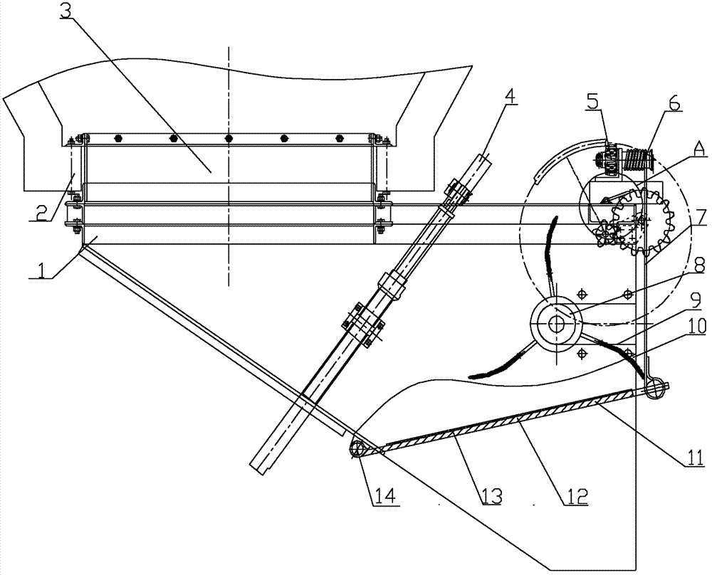
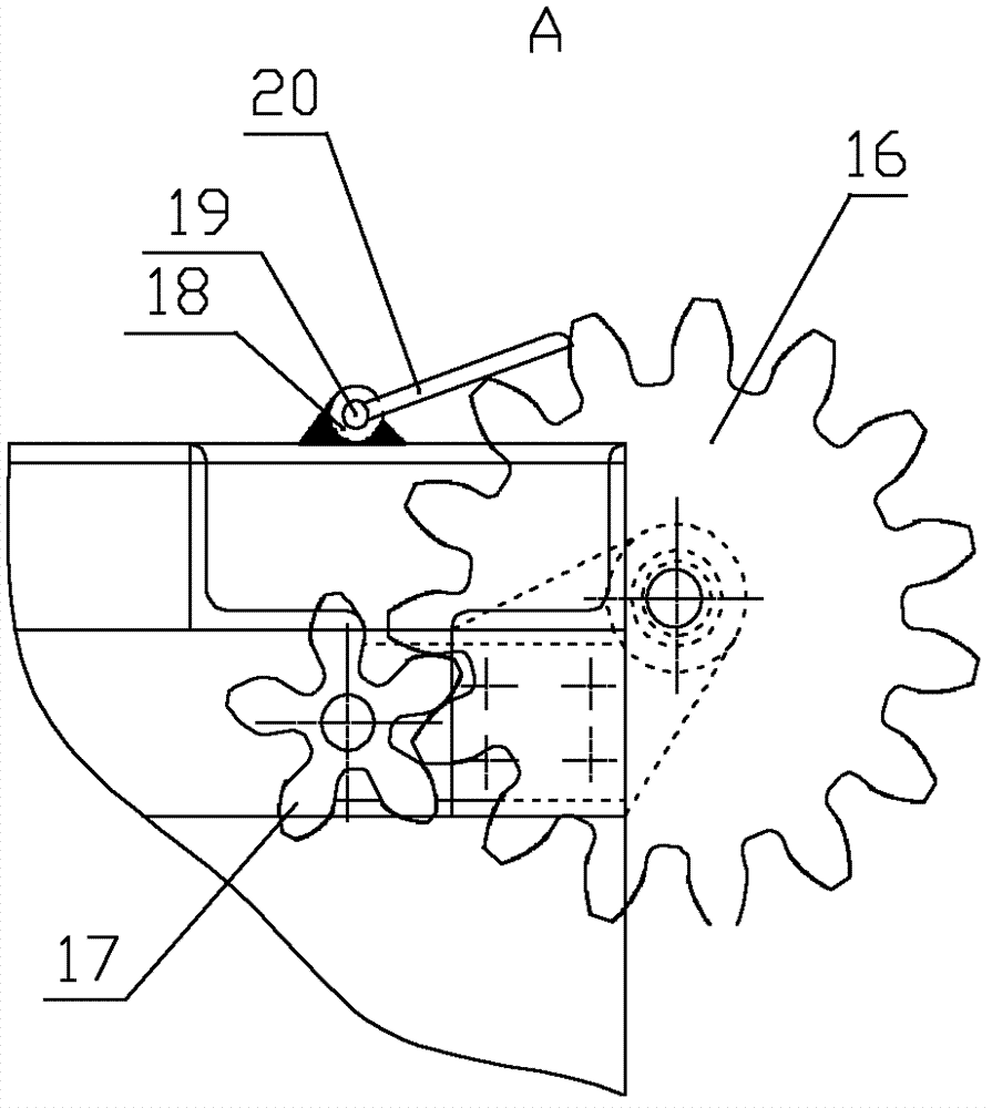
[0046] Figure 1 to Figure 8 It is the anti-shock rotary plate feeder described in Embodiment 1, which includes a material guide trough 1 and a rotating plate device 11, wherein the material guide trough 1 includes a material guide trough side plate 10 and a gate mechanism 4, and the material guide trough 1 is directly connected to the silo port 2, and the gate mechanism is set at the feed end of the material guide trough 1. The gate mechanism includes a gate, and the gate can be an obliquely inserted gate as shown in the figure, and the gate adopts a hydraulic cylinder mechanism. A rolling rake 8 is provided in the guide trough 1, and the rolling rake 8 includes a rake shaft and / or a rake cylinder, such as Figure 7 and Figure 8 As shown, the rake tooth 23 and the rake tooth holder 24 are detachably connected, and the shaft of the rake tooth 23 is inserted into the fixing hole of the rake tooth holder 24 for positioning. The surface of the rake shaft and / or the rake cylind...

Embodiment 2

[0053] Figure 9 It is the anti-shock rotary plate feeder described in Embodiment 2. The difference from Embodiment 1 is that: at the bottom of the feed trough 1, the joint and contact of the rotary plate and the feed trough are provided with a water-leakage coal chute 22 as shown in the figure, and the water-leakage coal chute 22 is inclined from It is arranged in a slippery shape, and it collects materials such as water and coal leaked from the gap between the hinge shaft 14 and the side plate 10 of the material guide trough 1 .

[0054] Others are with embodiment 1.

Embodiment 3

[0056] Figure 10 It is the anti-impact rotary plate feeder described in Embodiment 3. The difference from Example 1 is that the rake shaft and / or the rake cylinder are arranged on the side plate of the material guide trough 1, and two chutes 9 are arranged symmetrically on both sides of the material guide trough, and the rake shaft and / or the rake of the rolling rake Or the rake cylinder is arranged in the chute 9, and the chute 9 is an arc-shaped chute, and the rake shaft and / or the rake cylinder can be fixed in the chute 9, and can also slide along the chute 9.

[0057] Others are with embodiment 1.


PUM


Abstract

The invention belongs to the field of material delivery and particularly relates to a mining anti-impact rotating plate feeding machine. The feeding machine comprises a material guide groove and further comprises a rotating plate device which comprises a rotating lifting mechanism and a rotating plate. The material guide groove is directly connected with a bunker port, the rotating plate device is arranged in the material guide groove and avoids the feeding end of the material guide groove, the rotating plate device is hinged with the material guide groove, one end of the rotating plate is hinged with the material guide groove, and the rotating lifting mechanism drives the other end of the rotating plate to be lifted. The anti-impact rotating plate feeding machine achieves effective sealing of the material guide groove and the rotating plate device, greatly reduces adjusting resistance of the rotating plate, increases control flexibility, enables feeding quantity to be adjusted and controlled immediately and timely and achieves the aims of improving efficiency, saving energy and achieving optimum feeding transshipment.

Description

technical field [0001] The invention belongs to the field of material conveying, and in particular relates to a mine-used anti-shock rotating plate feeder. Background technique [0002] At present, commonly used feeders include belt feeders, reciprocating feeders, vibrating feeders, impeller feeders, scraper feeders, roller rake environmental protection, energy-saving and high-efficiency feeders, and no leakage Anti-blocking material environmental protection feeder, etc., the structure and existing problems of the above feeder are as follows: [0003] The structure and working state of the belt feeder are as follows: a ring-shaped conveyor belt is wound on two parallel rotating drums, and a certain number of rollers are arranged on the inner side of the ring-shaped conveyor belt between the two drums. The equipment is mainly composed of It consists of a connecting section, a material guide trough, a driving device, a transmission device, an annular conveying device and a ma...

Claims


Application Information

Patent Timeline
Patent Type & Authority Applications(China)
IPC IPC(8): B65G47/82
Inventor 刘素华
Owner 刘素华
Why Eureka
Try Eureka