
Ultraviolet fluid processor with double-layer cavity wall structure

A technology of ultraviolet rays and processors, which is applied in the direction of light water/sewage treatment, irradiation, etc., can solve the problems of high manufacturing cost of processors, and the lack of pressure resistance of rectangular processors, so as to reduce equipment costs and have little influence on fluid mixing dynamics , Improve the effect of processing capacity

Active Publication Date: 2013-05-08
FUJIAN NEWLAND ENTECH CO LTD
View PDF6 Cites 2 Cited by
  • Summary
  • Abstract
  • Description
  • Claims
  • Application Information

AI Technical Summary

Problems solved by technology

However, the rectangular processor is not pressure-resistant, and the wall thickness of the same pressure fluid medium is much larger than that of the cylindrical processor, and the manufacturing cost of the processor is huge. Therefore, a method that can avoid the influence of fluid mixing dynamics and provide a large Ultraviolet dose, large flow rate and high disinfection efficiency, and low-cost ultraviolet disinfection device to meet the demand

Method used


Image

  • Ultraviolet fluid processor with double-layer cavity wall structure
  • Ultraviolet fluid processor with double-layer cavity wall structure
  • Ultraviolet fluid processor with double-layer cavity wall structure

Examples


Embodiment 1

[0047] Embodiment 1 is an ultraviolet fluid processor in which the reactor cavity of the technical solution 1 of the present invention is a double-layer cavity wall structure.

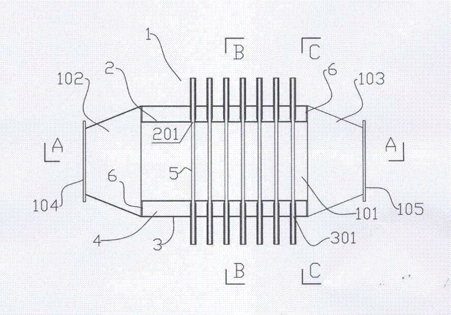
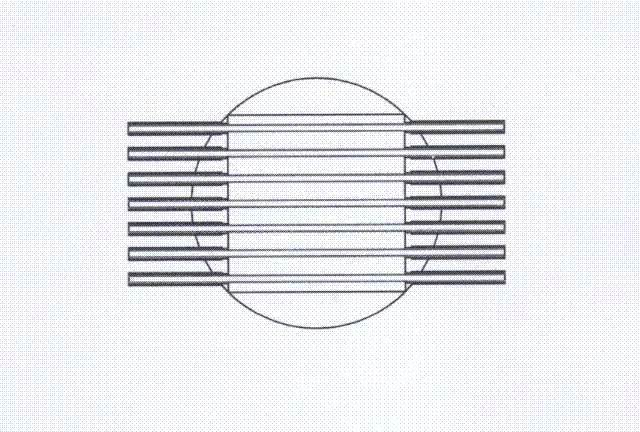
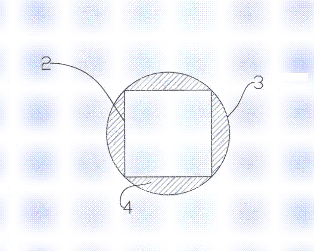
[0048] Such as Figure 1-4The shown reactor cavity is an ultraviolet fluid processor 1 with a double-layer cavity wall structure, including a reactor cavity 101, several ultraviolet lamp tubes and sleeves 5 thereof, two ends 106 of the reactor cavity 101 and 107 is provided with a fluid inlet 102 and a fluid outlet 103, and the outer sides of the fluid inlet 102 and the fluid outlet 103 are respectively provided with connecting devices 104 and 105. The reactor cavity 101 in this embodiment has a double-layer cavity wall structure. The reactor cavity of the double-layer cavity wall structure is composed of the outer cavity wall 3 and the inner cavity wall 2 installed inside the outer cavity wall. The inner cavity wall 2 is a square cross section with two ends open and the Closed circular cylinder. A c...

Embodiment 2

[0054] Embodiment 2 is an ultraviolet fluid processor in which part of the chamber of the reactor chamber of Scheme 2 of the present invention has a double-layer chamber wall structure.

[0055] Such as Figure 5-8 Part of the shown reactor cavity is an ultraviolet fluid processor 1 with a double-layer cavity wall structure, including a reactor cavity 101, several ultraviolet lamps and sleeves 5, and two of the reactor cavity 101 The ends 106 and 107 are provided with a fluid inlet 102 and a fluid outlet 103, and the outer sides of the fluid inlet 102 and the fluid outlet 103 are respectively provided with connecting devices 104 and 105, and part of the cavity of the reactor cavity 101 described in this embodiment is Double wall structure, part of the reactor cavity of the double wall structure is composed of an inner wall 2 and an outer wall 3, and the inner wall 2 is four partitions fixed on the inner side of the outer wall 202, each partition 202 and the outer cavity wall ...


PUM


Abstract

The invention provides an ultraviolet fluid processor with a double-layer cavity wall structure. The ultraviolet fluid processor comprises a reactor cavity body, a plurality of ultraviolet tubes and sleeves of the ultraviolet tubes; a fluid inlet and a liquid outlet are respectively formed at two end parts of the reactor cavity body; the reactor cavity body is provided with a double-layer cavity wall structure, or the reactor cavity body is partially provided with the double-layer cavity wall structure; the cavity body of the double-layer cavity wall structure consists of an inner cavity wall and an outer cavity wall; a cavity is formed between the inner cavity wall and the outer cavity wall; an opening is formed in the end part of the cavity, close to the fluid inlet of the reactor, and while the end part close to the fluid outlet of the reactor is sealed; a plurality of ultraviolet tube installing holes and sleeve installing holes are formed on the outer cavity wall; a plurality of ultraviolet tube installing holes and sleeve installing holes are also formed on the inner cavity wall, corresponding to the ultraviolet tube installing holes and the sleeve installing holes on the outer cavity wall; the ultraviolet tubes and the sleeves are arranged in the installing holes and are closed at the contact parts with respect to the inner cavity wall and the outer cavity wall.

Description

technical field [0001] The invention relates to an ultraviolet fluid processor with a double-layer cavity wall structure, which belongs to the field of ultraviolet fluid disinfection. Background technique [0002] From the perspective of current technology, due to the good pressure resistance of the circular cylinder, the main chamber of the reactor of the existing closed ultraviolet processor is usually a single-layer cylinder, and a fluid inlet and outlet is provided on the cylinder wall. The end is equipped with an ultraviolet lamp tube and its casing. The fluid flows into the cavity from the water inlet perpendicular to the direction of the ultraviolet lamp. After being irradiated by ultraviolet rays, it flows out from the water outlet perpendicular to the direction of the ultraviolet lamp. The irradiation effect is greatly affected by the fluid mixing dynamics of the medium. Especially when the diameter of the large-flow disinfection cavity is large, the influence of th...

Claims


Application Information

Patent Timeline
Patent Type & Authority Applications(China)
IPC IPC(8): C02F1/32A61L2/10
Inventor 陈健吴志军
Owner FUJIAN NEWLAND ENTECH CO LTD
Learn More