Film coating correction plate and assembly method thereof

An assembly method and a technology for correcting plates, which are applied in sputtering plating, ion implantation plating, vacuum evaporation plating, etc., can solve the problems of difficulty in guaranteeing the quality of the coating film, poor versatility, and low efficiency

Inactive Publication Date: 2013-05-08
FUYU PRECISION COMPONENTKUNSHANCO LTD
View PDF3 Cites 1 Cited by
  • Summary
  • Abstract
  • Description
  • Claims
  • Application Information

AI Technical Summary

Problems solved by technology

At present, the shape of the coating correction plate can depend on the shape of the substrate or the aluminum foil paper. The former foil wraps the substrate along the outline of the substrate. In this way, the shape of the coating correction plate is determined. When other shapes of the coating correction plate are required, it needs to be remade. , poor versatility
The latter’s alumi

Method used


Image

  • Film coating correction plate and assembly method thereof
  • Film coating correction plate and assembly method thereof
  • Film coating correction plate and assembly method thereof

Examples


Embodiment Construction

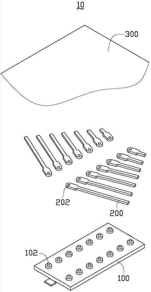
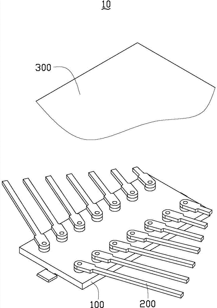
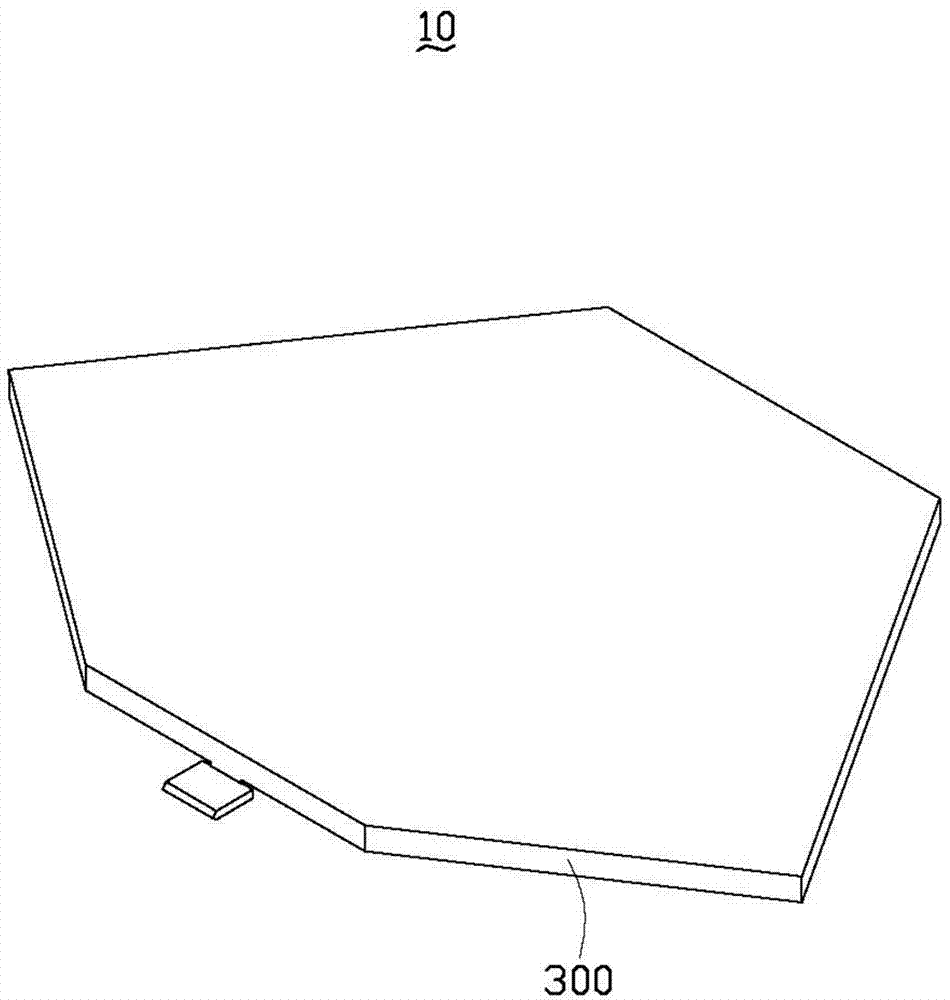
[0021] see Figure 1-4 , the coating correction plate 10 according to the preferred embodiment of the present invention includes a substrate 100 , at least one wing 200 with different lengths and an aluminum foil 300 . The at least one wing 200 is detachably and rotatably assembled to the substrate 100 . The aluminum foil paper 300 wraps the substrate 100 and the flap 200 assembled on the substrate 100 along the outer contour 400 of the substrate 100 and the flap 200 assembled on the substrate 100 .

[0022] Specifically, the coating correction plate 10 can be obtained through the assembly method of the coating correction plate in the preferred embodiment of the present invention, which includes:

[0023] providing the substrate 100, a plurality of wings 200 with different lengths and the aluminum foil 300;

[0024] Select at least one fin 200 from the plurality of fins 200 according to the coating requirements;

[0025] Select an assembly position from the substrate for ea...


PUM


Abstract

The invention provides a film coating correction plate which comprises a substrate, at least one wing panel with different lengths, and one aluminium foil paper, wherein the at least one wing panel can detachably and rotatably assembled on the substrate, the aluminium foil paper wraps the substrate and the at least one wing panel along an outer contour of the substrate and the at least one wing panel, thereby being capable of preventing influences of artificial tailoring on shapes of the film coating correction plate, improving quality and efficiency of the film coating, and being capable of changing shapes of the film coating correction plate to meet different demands. The invention further provides an assembly method of the film coating correction plate.

Description

technical field [0001] The invention relates to coating technology, in particular to a coating correction plate and an assembly method thereof. Background technique [0002] The coating machine includes a crucible and an umbrella frame set relative to the crucible. The umbrella frame is formed with multiple rings of receiving holes from the center to the edge, and each receiving hole accommodates one or more workpieces to be coated. During coating, the material in the crucible is bombarded by the electron beam after evaporation and reacts with the reaction gas, and then attaches to the workpiece to be coated to form a film layer, and the umbrella stand rotates so that the film gas obtained by the workpiece to be coated in the same circle of holding holes is basically the same , so that the film thicknesses of the workpieces to be coated in the same ring of receiving holes are basically the same. However, in general, the film gas concentration in several circles of holding ...

Claims


Application Information

Patent Timeline
IPC IPC(8): C23C14/24C23C14/54C23C14/04
CPCC23C14/044
Inventor 裴绍凯
Owner FUYU PRECISION COMPONENTKUNSHANCO LTD
Why Eureka
Try Eureka