Fault diagnosis method for switch reluctance motor dual-switch power converter fly-wheel diode

一种开关磁阻电机、续流二极管的技术,应用在二极管测试、测量电变量、电动发电机测试等方向,能够解决不能判断续流二极管故障类型和故障的位置、不具备续流二极管故障检测及故障定位功能等问题,达到诊断过程迅速、性价比高、效果好的效果

Active Publication Date: 2013-05-08
CHINA UNIV OF MINING & TECH
View PDF6 Cites 27 Cited by
  • Summary
  • Abstract
  • Description
  • Claims
  • Application Information

AI Technical Summary

Problems solved by technology

The freewheeling diode is one of the important components of the switched reluctance motor power converter, and it is an important guarantee for the phase commutation of the switched reluctance motor and the commutation of the main switch. It does not have the fault detection and fault location functions of the freewheeling diode. When the freewheeling diode of the power converter fails, the system cannot judge the fault type and location of the freewheeling diode

Method used


Image

  • Fault diagnosis method for switch reluctance motor dual-switch power converter fly-wheel diode
  • Fault diagnosis method for switch reluctance motor dual-switch power converter fly-wheel diode
  • Fault diagnosis method for switch reluctance motor dual-switch power converter fly-wheel diode

Examples


Embodiment Construction

[0024] The present invention will be further described below in conjunction with the embodiment in the accompanying drawings:

[0025] Taking a three-phase switched reluctance motor with dual main switch power converters per phase as an example, the diode fault diagnosis method of the present invention:

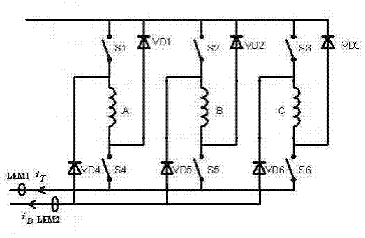
[0026] Such as figure 1 As shown, two current sensors are placed in each phase of the dual main switch power converter, and one current sensor LEM1 is used to detect the total current i of the main switch under the DC bus T , the other current sensor LEM2 is used to detect the total current i of the freewheeling diode under the DC bus D , the direction of the arrow in the figure is the positive direction of the current. Taking phase A as an example, when supplying power to the power converter, both the upper main switch and the lower main switch work normally without failure. No current can be detected;

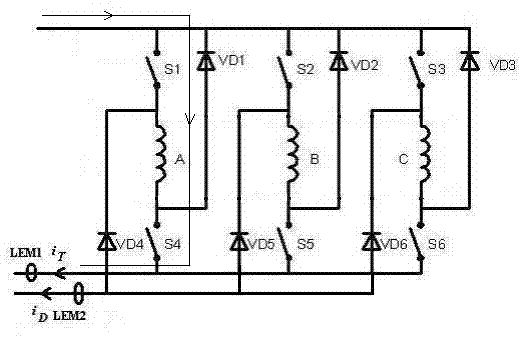
[0027] Such as figure 2 As shown, only the lower main switch S4 o...


PUM


Abstract

Disclosed is a fault diagnosis method for a switch reluctance motor each-phase dual-master-switch power converter fly-wheel diode. Two electric current sensors are assembled and placed in an each-phase dual-master-switch power converter. One electric current sensor LEM 1 is used for detection of direct current bus lower master switch total current. The other electric current sensor LEM2 is used for detection of total current feedback by a direct current bus lower fly-wheel diode. An upper master switch diode and a lower master switch diode are controlled to be broken-over and turned off so that conditions that the upper fly-wheel diode is in short-circuit fault, the lower fly-wheel diode is in short-circuit fault, the upper and the lower fly-wheel diodes are all in short-circuit fault, the upper fly-wheel diode is in open-circuit fault, the lower fly-wheel diode is in open-circuit fault, or the upper and the lower fly-wheel diodes are all in open-circuit fault can be judged. The fault diagnosis method for the switch reluctance motor each-phase dual-master-switch power converter fly-wheel diode is precise in detection of fly-wheel diode fault, discrimination of fault modes and location of fault phases. Convenience is brought to implementation of fault-tolerant control of the fly-wheel diodes.

Description

[0001] technical field [0002] The invention relates to a fault diagnosis method for a freewheeling diode of a power converter of a switched reluctance motor, which is suitable for power converters of double main switched reluctance motors with various phase numbers per phase. [0003] Background technique [0004] The dual main switched reluctance motor power converter for each phase is a unipolar power converter, which supplies unipolar current to the switched reluctance motor. The switched reluctance motor power converter is very prone to failure in harsh environments. Because each phase of the dual main switched reluctance motor power converter can make the phases on the magnetic circuit of the switched reluctance motor system and the system circuit independent of each other, when the switch When the reluctance motor system fails, it is convenient to adopt fault tolerance measures to realize the high reliability operation of the switched reluctance motor system in h...

Claims


Application Information

Patent Timeline
Patent Type & Authority Applications(China)
IPC IPC(8): G01R31/02G01R31/26G01R31/27
CPCG01R31/42G01R31/2632G01R31/024G01R31/34G01R31/40
Inventor 陈昊王星
Owner CHINA UNIV OF MINING & TECH
Why Eureka
Try Eureka