Device for adjusting position and angle of light beam

A technology of adjusting device and light beam, applied in the direction of exposure device, installation, optics, etc. of photoengraving process, can solve the problems of huge system, complex structure, high cost and maintenance difficulty, achieve high system utilization rate, simple maintenance, and improve system utilization rate effect

Active Publication Date: 2013-05-08
BEIJING GUOWANG OPTICAL TECH CO LTD
View PDF5 Cites 11 Cited by
  • Summary
  • Abstract
  • Description
  • Claims
  • Application Information

AI Technical Summary

Problems solved by technology

For lithography machines, too many optical paths and components will make the syst

Method used


Image

  • Device for adjusting position and angle of light beam
  • Device for adjusting position and angle of light beam
  • Device for adjusting position and angle of light beam

Examples


Embodiment Construction

[0019] The present invention will be further described below in conjunction with the accompanying drawings and implementation examples, but the protection scope of the present invention should not be limited thereby.

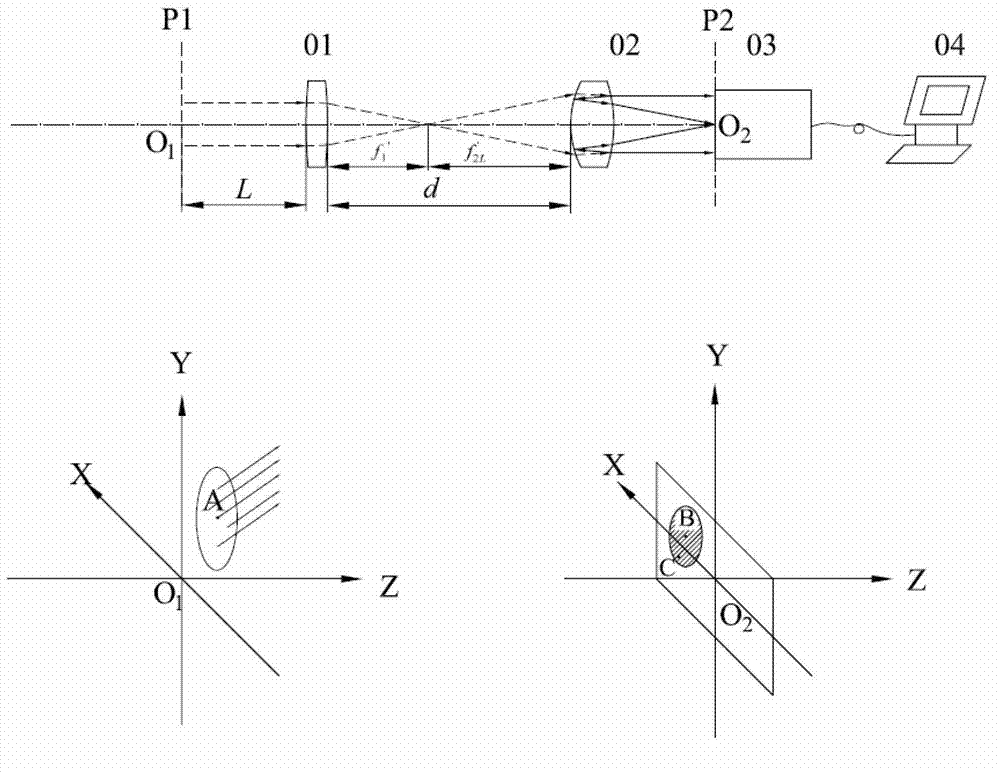
[0020] see first figure 1 , figure 1 It is a structural schematic diagram of the adjustment device for the beam position and angle of the present invention. As can be seen from the figure, the light beam position and angle measuring device of the present invention is composed of a common lens 01 along the forward direction of the light beam, a bifocal mirror 02, an image sensor 03 and a computer 04, the common lens 01 and the bifocal mirror 02 Long focal length confocal, the photosensitive surface of the image sensor 03 is located at the rear focal plane of the bifocal lens, and the output end of the image sensor 03 is connected to the input end of the computer 04 .

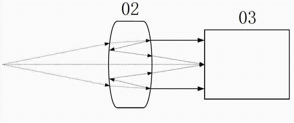
[0021] Bifocal 02 is a bifocal or a combination of an ordinary lens and a bifocal. Both surf...


PUM


Abstract

The invention discloses a device for adjusting position and angle of a light beam, wherein the device comprises a normal lens, a bifocal lens, an image sensor and a computer which are arranged in sequence along the forwards direction of the light beam. The focal points of the long focuses of the normal lens and the bifocal lens are the same focal point, the light-sensitive surface of the image sensor is located on the rear focal surface of the bifocal lens, the centre of the image sensor is located on the optical axis of a system, and the output end of the image sensor is connected with the input end of a computer. The device disclosed by the invention not only can accurately adjust the position and the angle of the light beam, but also has the advantages of simple structure and low cost.

Description

technical field [0001] The invention relates to the field of light beam alignment, and relates to a device for adjusting the position and angle of a light beam in an exposure system of a lithography machine. technical background [0002] Optical systems (especially large and complex optical systems) are extremely susceptible to various dynamic disturbances in the operating environment. Changes in ambient temperature, atmospheric turbulence, dust and smoke, and mechanical vibrations caused by various reasons will affect the optical system to varying degrees. The performance of the system may even cause the system to fail to work normally. Therefore, a high-precision beam position and angle adjustment mechanism is required in the development process of precision optical equipment. [0003] Taking the lithography machine as an example, in the exposure system of the lithography machine, there are many factors that may cause the laser output beam to deviate from the predetermined...

Claims


Application Information

Patent Timeline
IPC IPC(8): G03F7/20G02B7/02
Inventor 张善华曾爱军袁乔黄立华任冰强黄惠杰
Owner BEIJING GUOWANG OPTICAL TECH CO LTD
Why Eureka
Try Eureka