
Magnetostriction high-precision time measurement system based on electro-magnetic induction

A time measurement and magnetostrictive technology, which is applied in the direction of electrical unknown time interval measurement, devices and instruments for measuring time interval, etc.

Inactive Publication Date: 2013-05-08
NANJING UNIV OF AERONAUTICS & ASTRONAUTICS
View PDF6 Cites 6 Cited by
  • Summary
  • Abstract
  • Description
  • Claims
  • Application Information

AI Technical Summary

Problems solved by technology

However, most of the time measurement circuits of existing magnetostrictive displacement sensors use analog technology, and traditional analog methods are difficult to implement on integrated circuits. With the continuous development of semiconductor technology, embedded technology and EDA technology, digital design technology will gradually replace analog technology
The digital method uses synchronous clock pulses to count and measure the time interval. To improve the time measurement accuracy of the digital method, it is necessary to increase the frequency of the counting clock. However, the traditional TTL and CMOS logic circuits cannot work at a high frequency, so that The accuracy of the magnetostrictive displacement sensor is not high

Method used


Image

  • Magnetostriction high-precision time measurement system based on electro-magnetic induction
  • Magnetostriction high-precision time measurement system based on electro-magnetic induction
  • Magnetostriction high-precision time measurement system based on electro-magnetic induction

Examples


Embodiment Construction

[0018] Below in conjunction with accompanying drawing and specific embodiment this patent is described further as follows.

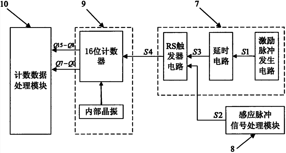
[0019] The invention is a magnetostrictive high-precision time measurement system based on electromagnetic induction applied to a magnetostrictive displacement sensor. The system includes four parts: a time interval acquisition module 7 , an induction pulse signal processing module 8 , a counting module 9 and a counting data processing module 10 .

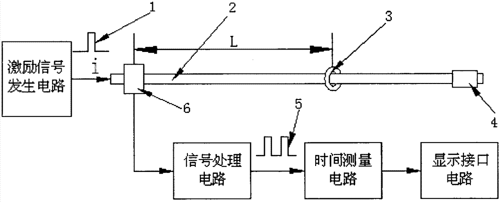
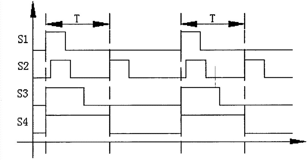
[0020] The circuit connection of each part of the present invention is as image 3 As shown, at first, the excitation pulse S1 is generated by the excitation pulse generation circuit in the time interval acquisition module 7, such as figure 1 As shown, after being amplified, it is applied to the waveguide wire 2 to generate a weak echo signal, which is input to the induction pulse signal processing circuit 8 after being amplified and filtered to eliminate the secondary echo 11 (such as Figure 4 Shown), get...


PUM


Abstract

The invention provides a magnetostriction high-precision time measurement system based on electro-magnetic induction and relates to the fields of electromagnetism, electronic technique, sensor technology and digital signal processing. According to the magnetostriction high-precision time measurement system based on electro-magnetic induction, firstly a time measurement sequence chart is designed according to an operating principle of a magnetostrictive displacement sensor, and then the magnetostriction high-precision time measurement system is built based on electro-magnetic induction on complex programmable logic device (CPLD). The magnetostriction high-precision time measurement system comprises a time interval acquisition module, an inductive pulse signal processing module, a counting module and a counted data processing module. The time interval acquisition module comprises a drive pulse generating circuit, a time-delay circuit and a remote sensing (RS) trigger circuit, and the counting module comprises a 16-digit counter and an inner crystal oscillator. The magnetostriction high-precision time measurement system based on electro-magnetic induction has the advantages that the functions are achieved by adopting the CPLD, high measurement precision can be achieved when the CPLD with a higher speed is adopted, and design flexibility of the circuits is improved. The accuracy of the magnetostrictive displacement sensor is improved due to the fact that the structure of the circuits is simplified, the cost is lowered, and equipment can be downsized easily.

Description

technical field [0001] The invention relates to the fields of electromagnetism, electronic technology, sensor technology, and digital signal processing, and in particular relates to the knowledge of magnetostrictive displacement sensor, electromagnetic induction, and high-precision time measurement technology based on electronic technology. Background technique [0002] The magnetostrictive displacement sensor uses the magnetostrictive torsional wave as the propagation medium to induce the magnetostrictive sensor. The sensor has the characteristics of non-contact measurement, high precision, good repeatability, stability and reliability, and strong environmental adaptability, and has been widely used in petroleum, chemical, pharmaceutical and other industries. [0003] Such as figure 1 As shown, the magnetostrictive displacement sensor generates a rotating magnetic field around the waveguide wire by applying a given excitation pulse to the waveguide wire. The position magn...

Claims


Application Information

Patent Timeline
Patent Type & Authority Applications(China)
IPC IPC(8): G04F10/04
Inventor 周翟和汪丽群胡佳佳沈超
Owner NANJING UNIV OF AERONAUTICS & ASTRONAUTICS
Learn More