

Universal serial bus (USB) charger circuit
A charger and circuit technology, applied in the field of circuits, can solve the problems of high failure rate and easy damage, and achieve the effect of practical function and simple structure
- Summary
- Abstract
- Description
- Claims
- Application Information
AI Technical Summary
Problems solved by technology
Method used
Image

Examples
Embodiment Construction
[0013] The present invention will be specifically described below in conjunction with the accompanying drawings and specific embodiments.
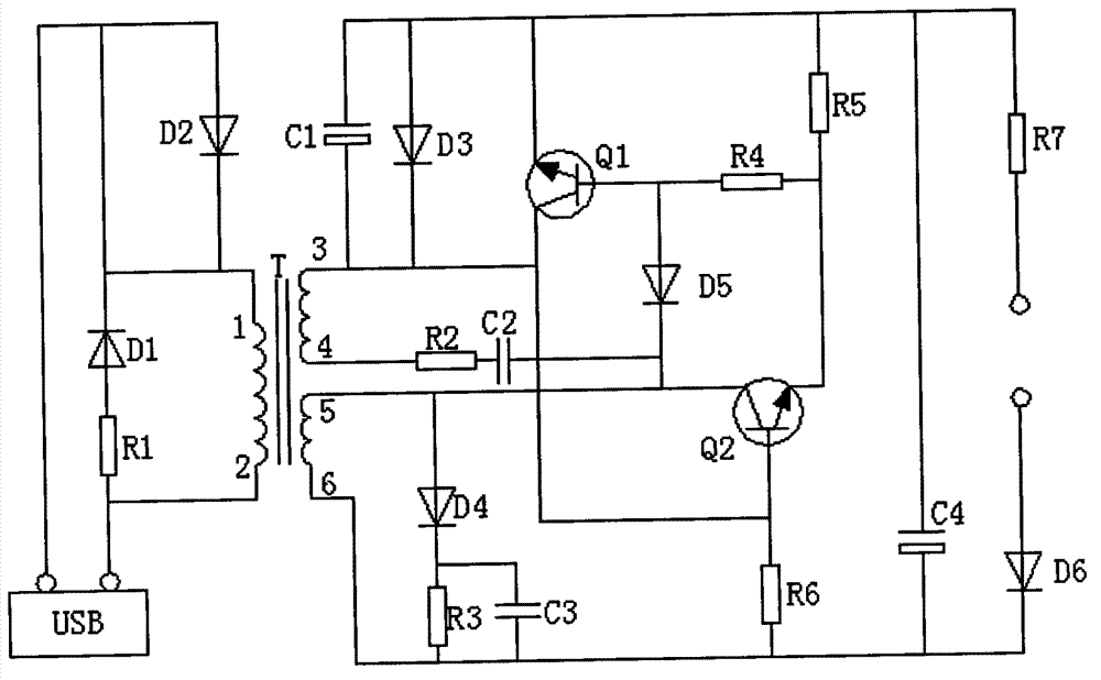
[0014] combine figure 1 As shown, a USB charger circuit of the present invention includes a transformer T, two transistors Q1-Q2, four capacitors C1-C4, six diodes D1-D6 and seven resistors R1-R7,
[0015] One end of the power input end is connected in series with the resistor R7 and then connected to the emitter of the transistor Q1, and the other end of the power input end is connected in series with the diode D6 and the resistor R6, and then connected to the collector of the transistor Q1 and the base of the transistor Q2, and the base of the transistor Q1 A diode D5 is connected in series between the collector of the transistor Q2, a resistor R4 is connected in series between the base of the transistor Q1 and the emitter of the transistor Q2, a resistor R5 is connected in series between the emitter of the transistor Q1 and the emitter ...
PUM
 Abstract
Description
Claims
Application Information