
Electronic device shell and manufacture method thereof

A technology for electronic devices and manufacturing methods, which is applied to electrical equipment casings/cabinets/drawers, chemical instruments and methods, telephone communications, etc., and can solve problems such as insufficient material hardness, single color, and no longer beautiful and eye-catching appearance.

Inactive Publication Date: 2013-05-08
SHENZHEN FUTAIHONG PRECISION IND CO LTD
View PDF3 Cites 22 Cited by
  • Summary
  • Abstract
  • Description
  • Claims
  • Application Information

AI Technical Summary

Problems solved by technology

[0003] There are two main types of portable electronic device casings at present. One is the metal casing, which has a relatively single color. Even if protective or decorative coatings such as baking varnish and electroplating are formed on the surface, it is often caused by improper collision during use. The phenomenon of skin peeling makes the appearance no longer beautiful and eye-catching; the other type is plastic shell, although there are many colors, but because the material is not hard enough, it is easy to scratch the surface of the shell during use and damage the original beautiful

Method used


Image

  • Electronic device shell and manufacture method thereof
  • Electronic device shell and manufacture method thereof
  • Electronic device shell and manufacture method thereof

Examples


Embodiment Construction

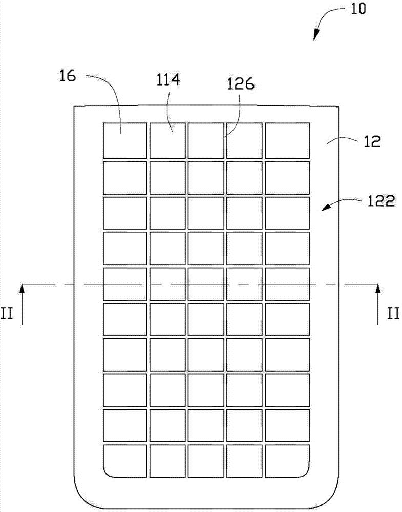
[0021] see figure 1 , the electronic device casing 10 according to the first embodiment of the present invention includes a metal base 12 and a first ceramic coating 14 and a second ceramic coating 16 formed on the surface of the metal base 12 .

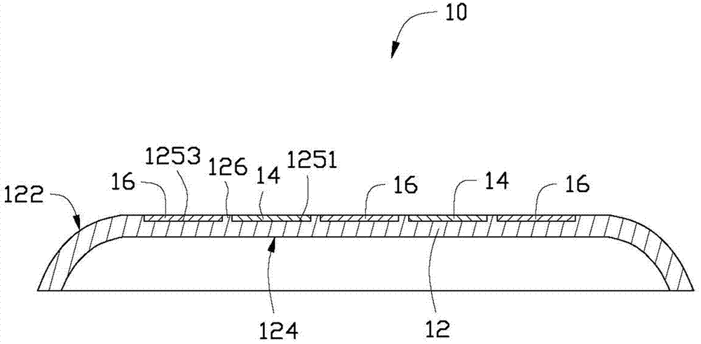
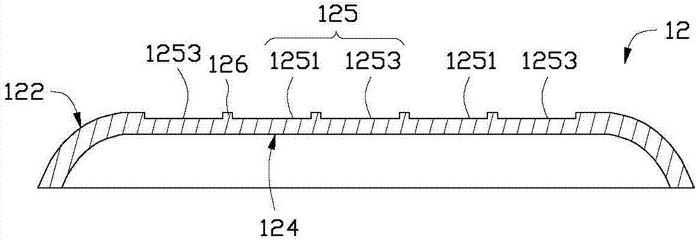
[0022] see figure 2 and image 3 , The metal base 12 can be made of metal such as stainless steel, aluminum alloy, etc., and its thickness is about 0.4~0.6mm, which is 0.5mm in this embodiment. The metal base 12 includes a first surface 122 and a second surface 124 opposite to the first surface 122 . A plurality of recesses 125 and protrusions 126 formed between the recesses 125 are formed on the first surface 122 . The surface of the concave portion 125 is lower than the surface of the convex portion 126 . The surface of the concave portion 125 is a rough surface, and its surface roughness Ra is approximately 1.3-2.0 μm. The concave portion 125 includes several first pattern areas 1251 and several second pattern areas 1253 . ...


PUM

PropertyMeasurementUnit
surface roughnessaaaaaaaaaa
thicknessaaaaaaaaaa
thicknessaaaaaaaaaa

Abstract

The invention provides an electronic device shell which comprises a metallic matrix body. The electronic device shell further comprises a first ceramic coating and a second ceramic coating which are formed on the surface of the metallic matrix body. The metallic matrix body comprises a first surface, a plurality of concave portions and protrusions which are formed between each two concave portions are formed on the first surface, each concave portion comprises a plurality of first pattern areas and a plurality of second pattern areas, the first ceramic coating covers the first pattern areas, the second ceramic coating covers the second pattern areas, and the first ceramic coating and the second ceramic coating are of different colors. The invention further provides a manufacture method of the electronic device shell.

Description

technical field [0001] The invention relates to an electronic device casing, in particular to an electronic device casing with a ceramic coating on the surface and a manufacturing method thereof. Background technique [0002] With the rapid development of wireless communication and information processing technology, portable electronic devices such as mobile phones and personal digital assistants (PDA) are emerging, allowing consumers to fully enjoy the convenience brought by high technology anytime and anywhere. In addition to updating and expanding the functions of these portable electronic devices, they are constantly being updated in appearance and shape as they become popular and user preferences. [0003] There are two main types of portable electronic device casings at present. One is the metal casing, which has a relatively single color. Even if protective or decorative coatings such as baking varnish and electroplating are formed on the surface, it is often caused b...

Claims


Application Information

Patent Timeline
Patent Type & Authority Applications(China)
IPC IPC(8): H05K5/00B32B3/30B32B15/04B32B18/00
CPCC23C4/18H04M1/0283C23C4/105H04M1/0249B32B15/04C23C4/02B32B18/00H05K5/00B32B3/30H05K5/0243C23C4/11Y10T29/49986Y10T428/1317
Inventor 朱永刚
Owner SHENZHEN FUTAIHONG PRECISION IND CO LTD
Learn More