
Power supply system

A technology of a power supply system and a power supply device, applied in the field of power supply systems, can solve the problems of increasing the capacity of the air conditioning system, increasing the burden of the air conditioning system, increasing the cost of the air conditioning system, etc., and achieving the effect of ensuring a constant temperature environment and reducing the increase in cost.

Inactive Publication Date: 2013-05-08
BRILLIANT LIGHT TECH
View PDF3 Cites 0 Cited by
  • Summary
  • Abstract
  • Description
  • Claims
  • Application Information

AI Technical Summary

Problems solved by technology

[0003] A large amount of heated gas discharged from the power supply device will add a lot of burden to the air conditioning system of the clean room, so the capacity of the air conditioning system needs to be increased, resulting in an increase in the cost of the air conditioning system; usually the clean room requires a constant temperature within a certain temperature range However, a large amount of heated gas discharged from the power supply device destroys the constant temperature environment in some parts of the clean room, which has a negative impact on the process preparation of semiconductors
[0004] Therefore, how to provide a cooling technology for the power supply unit of semiconductor equipment, to reduce or eliminate the problem of destroying the constant temperature environment of the clean room in the prior art, has become a technology that those skilled in the art need to solve

Method used


Image

  • Power supply system
  • Power supply system
  • Power supply system

Examples


Embodiment Construction

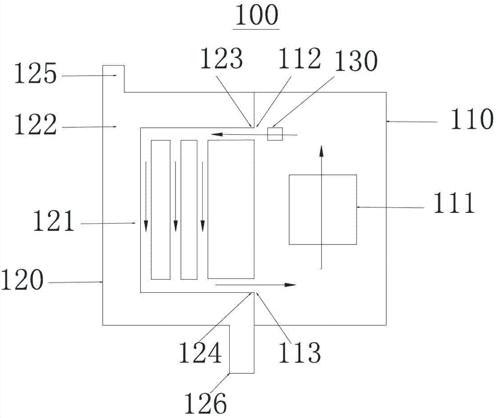
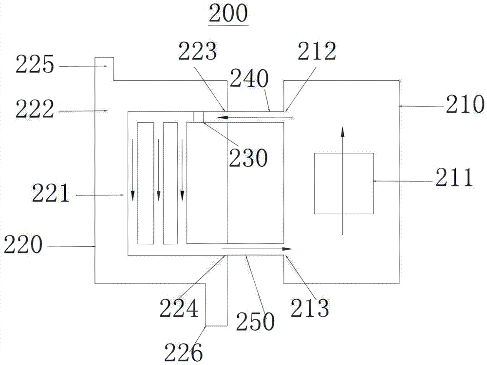
[0027] In the power supply system of the prior art, the gas heated by the heat generated by the power module due to work is directly discharged into the clean room where the semiconductor equipment is installed, thereby destroying the constant temperature environment of the local part of the clean room, and This leads to an increase in the cost of the air conditioning system. After in-depth research on the power supply system in the prior art, the inventor found that a cooling device is mounted on the power supply device, and the cooling device includes a first channel and a second channel in contact with the first channel for heat exchange , the second channel has an external circulating cooling liquid; the first channel communicates with the power supply unit to form a gas circulation circuit, and a circulation unit is arranged in the gas circulation circuit, and a circulation unit is installed in the circulation unit Under the action, the gas circulates in the gas circulati...


PUM


Abstract

The invention relates to a power supply system which comprises a power supply device, and a cooling device, wherein the power supply device is used for providing direct current power supply for a semiconductor device, a power supply module is arranged inside the power supply device, and air heated by the heat produced by the power supply module when the power supply module works is in the power supply device, the cooling device is arranged on the power supply device, the cooling device comprises a first channel and a second channel which is contacted with the first channel to conduct heat exchange, external cooling liquid in circular flow is filled in the second channel, the first channel and the power supply device are communicated with each other to form an air circulating loop, the air flows in circle in the air circulating loop under the effect of a circulating unit, the heated air flows to the first channel through the power supply device, and heat is transmitted to the cooling liquid in the second channel. After the air is cooled, the air flows back to the power supply device, so that cooling for the power supply module is achieved, and the heated air is prevented from being discharged to a clean room.

Description

technical field [0001] The invention relates to a power supply device for providing DC power to semiconductor equipment, in particular to a power supply system. Background technique [0002] Semiconductor equipment in the clean room, such as metal-organic chemical vapor deposition (Metal-organic Chemical Vapor Deposition, referred to as MOCVD) and other equipment, requires a special power supply unit to provide DC power, and the power supply unit has a high-power DC power supply module , the power module will generate a large amount of heat energy during operation and cause the temperature of the power module to rise. If the temperature of the power module is too high, the working efficiency of the power module will be reduced or even the power module will be burned. In order to ensure that the power module can work normally, the power module has its own cooling fan, and the function of the cooling fan is to draw cooling gas into the power module (the cooling gas is the gas ...

Claims


Application Information

Patent Timeline
Patent Type & Authority Applications(China)
IPC IPC(8): H05K7/20
Inventor 张义明陈力兵祝龙飞房伟
Owner BRILLIANT LIGHT TECH
Learn More