Electric shock absorbers for motor vehicles

A technology for shock absorbers and motor vehicles, applied in liquid shock absorbers, springs/shock absorbers, mechanical equipment, etc. Effect

Inactive Publication Date: 2015-11-25
AUDI AG
View PDF8 Cites 0 Cited by
  • Summary
  • Abstract
  • Description
  • Claims
  • Application Information

AI Technical Summary

Problems solved by technology

However, due to this normally small rotational movement of the rotor, force peaks that may occur in special driving situations are extremely perceptible due to the low homogeneity of the magnetic field in the generator

Method used


Image

  • Electric shock absorbers for motor vehicles
  • Electric shock absorbers for motor vehicles
  • Electric shock absorbers for motor vehicles

Examples


Embodiment Construction

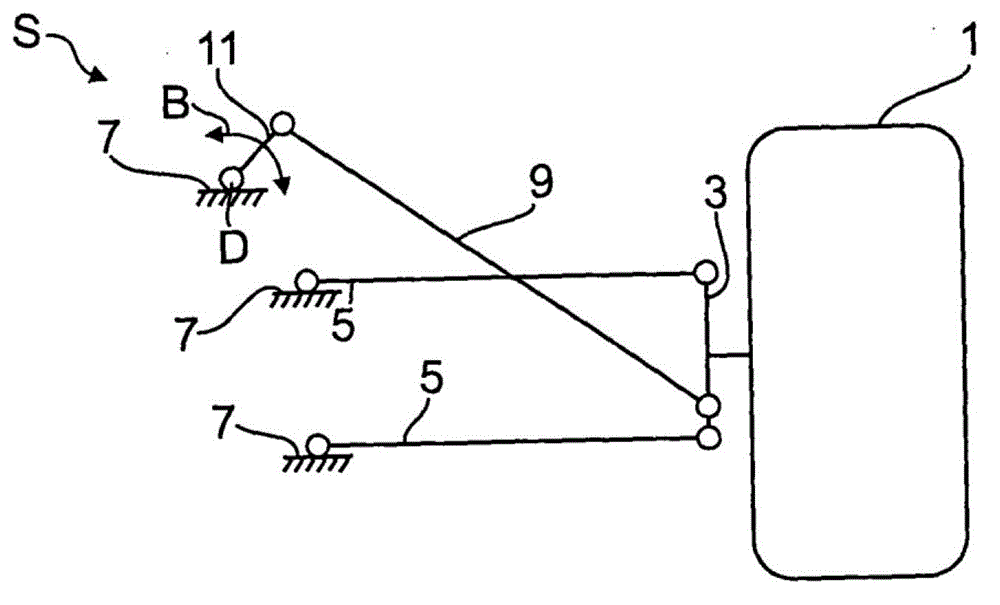
[0024] figure 1 shows a wheel suspension for a wheel 1 of a motor vehicle. The wheel 1 is rotatably supported on a hub carrier 3 . The hub carrier 3 is articulated to the motor vehicle body 7 via a transverse control arm 5 . In addition, the tilt control arm 9 acts on the hub carrier 3 , which is connected to the motor vehicle body 7 via a coupling 11 . exist figure 1 In this case, the coupling 11 is connected to the motor vehicle body 7 in an articulated position S in a rotationally articulated manner about the pivot axis D.

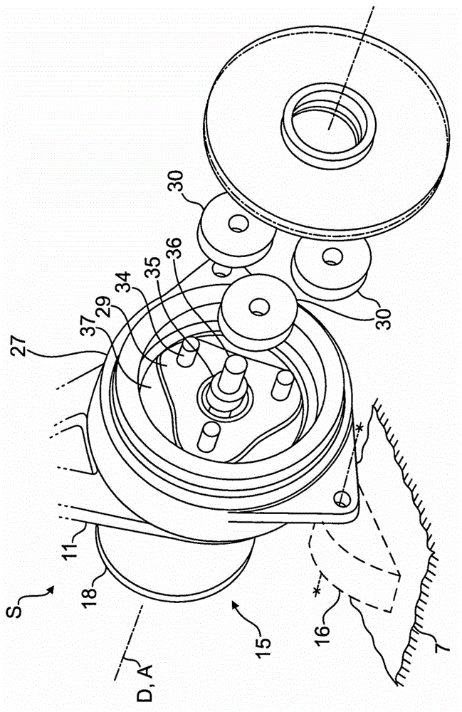
[0025] exist figure 2 In , the articulation point S between the coupling 11 and the motor vehicle body 7 is enlarged and shown in a partially exploded view. The coupling 11 has a fastening eye 13 which is fixed via an electric shock absorber 15 on a retaining bracket 16 shown only in dashed lines, like figure 2 as shown in.

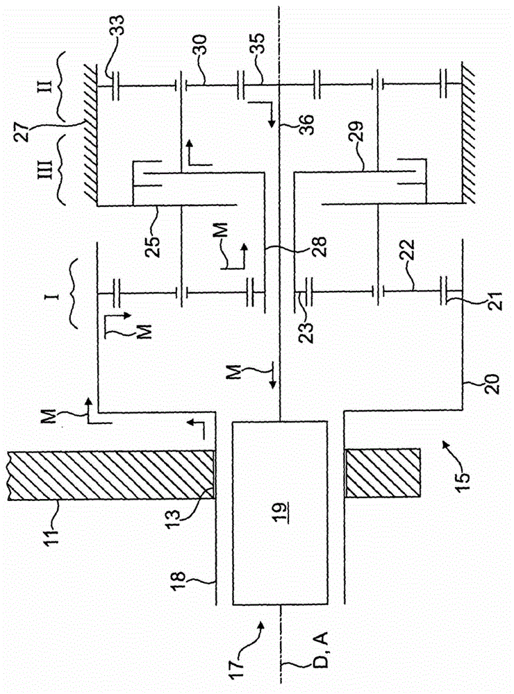
[0026] according to image 3 , the electric shock absorber 15 has a rotating field generator 17 comprising a radially o...


PUM


Abstract

The invention relates to an electric damper for a vehicle for damping mechanical vibrations (B) arising between two components (7, 11), wherein by means of said mechanical vibrations drive torques can be transmitted in a torque flow direction (M) to an electrical generator (17) in order to generate an induced voltage. According to the invention, an in particular hydraulic damping stage (III) that dampens high-frequency vibration components is arranged upstream of the generator (17) in the torque flow direction (M).

Description

technical field [0001] The invention relates to an electric shock absorber for a motor vehicle. Background technique [0002] Such an electric shock absorber can be used in place of a hydraulic shock absorber in a vibrating mechanical system of a motor vehicle. Like hydraulic shock absorbers, electric shock absorbers also absorb the energy of a vibrating system. However, this energy is not converted into heat energy. Instead, the vibration energy is used to drive a generator associated with the electric shock absorber, which converts the vibration energy into electrical energy that can be supplied to the on-board electrical system of the motor vehicle. [0003] An electric shock absorber for a motor vehicle is known from DE 10115858 A1 for damping mechanical vibrations occurring between two components. The mechanical vibrations are converted into a drive torque with which a generator for generating the induced voltage can be driven. [0004] In the electric shock absorbe...

Claims


Application Information

Patent Timeline
Patent Type & Authority Patents(China)
IPC IPC(8): B60G13/14F16F9/12F16F15/03
CPCF16F15/035B60G13/14B60G2202/22B60G2204/128B60G2204/4191B60G2204/421B60G2300/60F16F9/12
Inventor M·威莱姆斯
Owner AUDI AG
Why Eureka
Try Eureka