Powertrain semi-active particle damping rubber mount

A particle damping and powertrain technology, applied in the field of auto parts, can solve problems such as high cost, low reliability, and large power consumption, and achieve the effects of low cost, convenient manufacturing, and simple and reliable structure

Inactive Publication Date: 2016-08-17
WUHAN UNIV OF SCI & TECH
View PDF6 Cites 0 Cited by
  • Summary
  • Abstract
  • Description
  • Claims
  • Application Information

AI Technical Summary

Problems solved by technology

The response speed of the active mount is fast, and its vibration isolation performance is better than that of the semi-active mount, but it has the disadvantages of complex system, high power consumption, high cost, low reliability and inconvenient installation. Currently, it is rarely used in real vehicles application

Method used


Image

  • Powertrain semi-active particle damping rubber mount

Examples


Embodiment 1

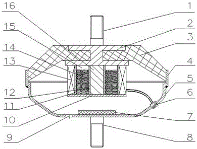
[0028] A powertrain semi-active particle damping rubber mount. Such as figure 1 Shown: the upper connecting bolt 1 of this embodiment is connected with the powertrain, and the lower connecting bolt 8 is connected with the vehicle frame. The upper plane of the connecting frame 2 is fixed with the upper connecting bolt 1, and the middle position of the rubber spring 3 is coaxially embedded in the connecting frame 2. The outer wall of the opening end of the rubber spring 3 is vulcanized and bonded to the steel ring 4, and the opening end of the rubber spring 3 passes through the The steel ring 4 is fixedly connected to the open end of the suspension housing 5 . The inner side of the bottom of the suspension housing 5 is provided with a buffer pad 7 , the housing of the suspension housing 5 is provided with a communication hole 9 , and the outer side of the bottom of the suspension housing 5 is fixed with a lower connecting bolt 8 .

[0029] The lower end of the outer steel pipe...

Embodiment 2

[0040] A powertrain semi-active particle damping rubber mount. Except following technical parameter, all the other are identical with embodiment 1.

[0041] The diameter of the steel ball 14 is 0.1-1mm.

[0042]The material of the rubber spring 3 is nitrile rubber.

[0043] The loaded amount of the steel ball 14 is 60-70% of the volume of the damping cavity 15 .

[0044] The shape of the outer steel pipe 11 and the shape of the inner steel pipe 12 are both oval pipes.

Embodiment 3

[0046] A powertrain semi-active particle damping rubber mount. Except following technical parameter, all the other are identical with embodiment 1.

[0047] The operating voltage of the electromagnetic coil 13 is 24V.

[0048] The diameter of the steel ball 14 is 1-3 mm.

[0049] The material of the rubber spring 3 is neoprene.

[0050] The loaded amount of the steel ball 14 is 70-80% of the volume of the damping chamber 15 .

[0051] The shape of the outer steel pipe 11 and the shape of the inner steel pipe 12 are both polygonal pipes.


PUM


Abstract

The invention relates to a semi-active particle damping rubber mount for a power assembly. The technical solution is: the middle position of the rubber spring (3) is coaxially embedded in the connecting frame (2), and the opening end of the rubber spring (3) passes through the steel ring (4) and the opening end of the suspension housing (5) opposite fixed connection. The upper end surface and the lower end surface of the outer steel pipe (11) and the inner steel pipe (12) are connected coaxially with the lower plane of the connecting frame (2) and the upper plane of the bottom plate (10), and steel balls ( 14), the load of steel ball (14) is 50~80% of damping chamber (15) volume. An electromagnetic coil (13) is installed on the outer wall of the outer steel pipe (11), and the electromagnetic coil (13) is located on the upper plane of the base plate (10); the electromagnetic coil (13) passes through the coil socket (6) fixed on the suspension housing (5) The controller of the external suspension assembly, the coil socket (6) is fixed on the suspension housing (5). The invention has the characteristics of simple and reliable structure, convenient manufacture and low cost, and has the performances of broadband vibration isolation, vibration reduction and noise reduction.

Description

technical field [0001] The invention belongs to the technical field of auto parts. In particular, it relates to a powertrain semi-active particle damping rubber mount. Background technique [0002] In recent years, automobile design has developed towards light weight and economy, but the application of fewer cylinders, high-power engines and lightweight frame (body) will lead to intensified vibration transmitted from the engine to the body, deteriorating the vibration and noise characteristics in the car . Especially for front-engine-front-wheel-drive cars with poorly balanced four-cylinder four-stroke engines, the vibration of the powertrain has an increasingly prominent impact on the ride comfort of the car. At the same time, people's requirements for riding comfort are constantly improving. In order to solve these contradictions, it is necessary to improve the isolation effect of the powertrain mount on the vibration transmission between the powertrain and the vehicle ...

Claims


Application Information

Patent Timeline
Patent Type & Authority Patents(China)
IPC IPC(8): F16F9/04F16F9/44
Inventor 胡溧杨啟梁郭健忠游彩霞许小伟
Owner WUHAN UNIV OF SCI & TECH
Why Eureka
Try Eureka