Extraction method of kinesiology parameters

A technology of kinematic parameters and human motion, applied in the field of extraction of human kinematic parameters, can solve the problems of high price, complicated operation, complex calculation, etc., and achieve the effect of easy operation, simple method and low cost

Active Publication Date: 2013-05-15
INST OF AUTOMATION CHINESE ACAD OF SCI
6 Cites 24 Cited by

AI-Extracted Technical Summary

Problems solved by technology

Although this method has been studied in depth, it still faces huge challenges, such as the computational complexity brought by high-dimensional human motion state parameters, human body occlusion and self-occlusion, and the determination of parameters of the initial frame human body.
Therefore, this method cannot be effectively applied to medical 3D gait analysis in a short period of time.
[0005] At pr...

Method used

Fig. 1 has provided the general block diagram of human body kinematics parameter extraction method in the present invention, as seen in the figure, this method comprises the generation of camera calibration, head apex initial location, head apex three-dimensional movement trajectory, trajectory standardization processing, motion Five steps such as learning parameter extraction. In addition, the input data is a sequence of human linear motion images collected by multiple cameras synchronously; the human linear motion images collected by each camera are subjected to distortion correction operations before further processing to eliminate image dist...

Abstract

The invention discloses an extraction method of kinematics parameters based on head-top-point three-dimensional motion trails. The extraction method includes calibrating internal parameters and lens distortion coefficients of multi-view cameras, calibrating space position relationship among the multi-view cameras, positioning an initial position of the head-top-point of a human body, obtaining the three-dimensional motion trails of the head-top-point of the human body in a three-dimensional space by tracking the motion trails of the head-top-point in a human body motion image according to the mapping relation between a three-dimensional world coordinate system and a two-dimensional image coordinate system in a multi-view system, carrying out standard preprocessing on the three-dimensional motion trails of the head-top-point of the human body to obtain height waving information and swinging motion information in motion of the human body, and extracting the kinematics parameters from the height waving information and the swinging motion information. The extraction method is beneficial for barrier diagnosis of pathology gaits, formulation of a rehabilitation treatment scheme and therapeutic effect evaluation in clinical rehabilitation medicine.

Application Domain

Technology Topic

Image

  • Extraction method of kinesiology parameters
  • Extraction method of kinesiology parameters
  • Extraction method of kinesiology parameters

Examples

  • Experimental program(1)

Example Embodiment

[0022] In order to make the objectives, technical solutions, and advantages of the present invention clearer, the following further describes the present invention in detail in conjunction with specific embodiments and with reference to the accompanying drawings.
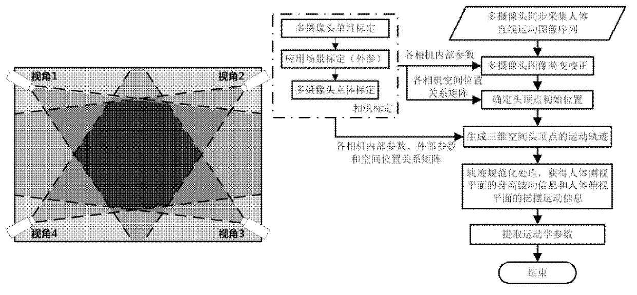
[0023] figure 1 The general block diagram of the method for extracting human kinematics parameters in the present invention is given. It can be seen from the figure that the method includes camera calibration, initial positioning of head vertices, generation of head vertices three-dimensional motion trajectory, trajectory normalization processing, and kinematic parameter extraction. Steps. In addition, the input data is a human body linear motion image sequence collected by multiple cameras synchronously; the human body linear motion images collected by each camera undergo a distortion correction operation before further processing to eliminate image distortion caused by the lens. The steps of the present invention will be further described in detail below in conjunction with the relevant drawings:
[0024] Step 1: Camera calibration, which is to calibrate the internal parameters and lens distortion coefficients of each camera and the spatial position relationship between the cameras to establish the mapping relationship between the ground 3D world coordinate system and the 2D image coordinate system in the multi-camera vision system .
[0025] Set the entire working range to 6m×4m. For this field of view, choose a lens with a moderate field of view. Taking these factors into consideration, a lens with a focal length of 6mm is selected. Four cameras are selected in the scene, and their position layout is as attached figure 1 As shown on the left, the four cameras are respectively arranged at viewing angles 1-4, and the camera with viewing angle 1 is used as the reference camera.
[0026] See attached figure 2 As shown in the figure, the camera calibration mainly involves four coordinate systems, namely the three-dimensional world coordinate system X w Y w Z w (The origin is on the ground, and Z w Axis perpendicular to the ground), 3D camera coordinate system X c Y c Z c (The origin is at the optical center of the lens, and Z c Axis coincides with the optical axis), two-dimensional image physical coordinate system xO 1 y (the origin is at the center of the image, and the coordinates are physical coordinates), the two-dimensional image pixel coordinate system uOv (the origin is at the upper left corner of the image, and the coordinates are pixel coordinates).
[0027] As attached figure 2 As shown, the linear camera pinhole model is used to define the coordinates of the space point P in the three-dimensional world coordinate system as [X m Y w Z w ] T , The corresponding homogeneous coordinates are P=[X w Y w Z w 1] T; Define the coordinates of point P in the three-dimensional camera coordinate system as [X c Y c Z c ] T , Whose homogeneous coordinates are P c =[X c Y c Z c 1] T; The projection point of the definition point P on the two-dimensional image plane is p′, and the coordinates of the two-dimensional image physical coordinate system are [x y] T (Unit: mm), the coordinates in the two-dimensional image pixel coordinate system are [u v] T , Its homogeneous coordinate is p′=[uv1] T. The intersection of the camera's optical axis and the image plane O 1 The pixel coordinates are [u 0 v 0 ] T; The physical dimensions of the image unit pixel in the x-axis and y-axis directions are dx and dy, respectively. Then the mapping relationship between the coordinates of the point P in the three-dimensional coordinate system and the coordinates of the two-dimensional image coordinates of the projection point p′ on the two-dimensional image plane is:
[0028] Z c u v 1 = f dx 0 u 0 0 0 f dy v 0 0 0 0 1 0 R t O t 1 X w Y w Z w 1 - - - ( 1 )
[0029] = a x 0 u 0 0 0 a y v 0 0 0 0 1 0 R t O t 1 X w Y w Z w 1 = M 1 M 2 P = MP
[0030] Among them, P=[X w Y w Z w 1] T Is the homogeneous coordinates in the three-dimensional world coordinate system; f is the focal length of the lens, a x = F/dx, a y =f/dy is the focal ratio of the camera, R and t are the rotation matrix and translation matrix between the three-dimensional camera coordinate system and the three-dimensional world coordinate system; O t =[000], M 1 , M 2 They are the camera's internal parameter matrix and external parameter matrix (that is, the homography matrix), and M is the overall projection matrix of the camera.
[0031] During the entire calibration process, the internal parameters of the camera need to be calibrated [f dx dy u 0 v 0 ] T And, camera lens distortion coefficient [k 1 k 2 p 1 p 2 k 3 ] T And external parameters, the internal parameters include the focal ratio of the camera, the position of the center point, and the external parameters include the rotation matrix R and the translation vector t between the three-dimensional camera coordinate system and the three-dimensional world coordinate system. In the calibration process, a black and white square grid calibration board is used for calibration. Among them, a small calibration board is used when calibrating internal parameters. The grid size is 50mm×50mm, and the number of grids is 8 (width)×12 ( Length); When calibrating external parameters, use a large calibration board with a grid size of 100mm×100mm, and the number of grids is 4 (width) × 6 (length). The Harris corner detection algorithm is used to detect the corner points on the calibration board, and the sub-pixel corner position is obtained.
[0032] Step 1 specifically includes the following steps:
[0033] Step 1-1: Perform single target positioning for each camera, and obtain the internal parameter and external parameter matrix of each camera.
[0034] (a) First obtain the initial internal parameters of each camera and the rotation matrix and translation vector of the camera relative to the small calibration plate.
[0035] Take the reference camera calibration as an example. In order to obtain the internal parameter matrix of the camera, firstly, the lens distortion is not considered, and the calibration method based on the planar homography matrix is ​​adopted. The small calibration board is held in hand, and the attitude of the small calibration board is constantly changed (at least 3 poses) , Using the plane matching between different viewpoints (direct linear transformation method) to calculate the initial internal parameters of the camera and the rotation matrix and translation vector of the camera relative to the small calibration plate; that is, the internal parameters of the camera and the camera relative to the zero lens distortion The rotation matrix and translation vector of the small calibration plate. Make the plane Z where the small calibration board is located w =0, then:
[0036] Z c u v 1 = a x 0 u 0 0 0 a y v 0 0 0 0 1 0 R t O t 1 X w Y w 0 1 = a x 0 u 0 0 a y v 0 0 0 1 R t X w Y w 0 1 0 , 1
[0037] = a x 0 u 0 0 a y v 0 0 0 1 r 1 r 2 r 3 t X w Y w 0 1 = a x 0 u 0 0 a y v 0 0 0 1 r 1 r 2 t X w Y w 1 - - - ( 2 )
[0038] = H · X w Y w 1
[0039] Among them, R=[r 1 r 2 r 3 ].
[0040] Therefore, the calibration of the reference camera can be completed by solving the H matrix, and the internal parameters of the camera itself and the rotation matrix and translation vector of the camera relative to the small calibration plate are obtained.
[0041] (b) Based on the initial internal parameters of the camera and the rotation matrix and translation vector of the camera relative to the small calibration plate, the lens distortion is considered, the distortion coefficient of the camera lens is further calculated, and the internal parameters of the camera are further optimized.
[0042] Let the image pixel coordinates of a certain corner point detected in the original lens distortion image be [u raw v raw ] T , The image pixel coordinate of the corner point in the image without lens distortion under the ideal pinhole imaging model is [u und v und ] T , Where the original lens distortion image is the image obtained by the camera lens; then:
[0043] (1) Transform the three-dimensional world coordinates of the corner points on the small calibration board to the three-dimensional camera coordinate system, where a corner point on the small calibration board is used as the origin to establish a three-dimensional world coordinate system, and then according to the small calibration board The length of the black and white grid is calculated to obtain the three-dimensional world coordinates of the corner points on the calibration board. which is
[0044] X c Y c Z c = R X w Y w Z w 1 + t - - - ( 3 )
[0045] Among them, R and t are the rotation matrix and translation vector of the camera relative to the small calibration plate.
[0046] (2) Further project to the image plane to obtain the undistorted image physical coordinates of the corner points in the image plane coordinate system [x und y und ] T And image pixel coordinates [u und v und ] T , which is
[0047] x und y und = fX c / Z c fY c / Z c - - - ( 4 )
[0048] u und v und = a x 0 u 0 0 a y v 0 0 0 1 x und y und - - - ( 5 )
[0049] (3) The image pixel coordinates of the corner points detected in the original lens distortion image (u raw v raw ] T Transform to image physical coordinates [x raw y raw ] T , And introduce a certain initial lens distortion coefficient [k 1 k 2 p 1 p 2 k 3 ] T , Get the pixel coordinates of the corner image after distortion correction [u′ und v′ und ] T And image physical coordinates [x′ und y′ und ] T , which is
[0050] x raw y raw 1 = dx 0 - u 0 dx 0 dy - v 0 dy 0 0 1 u raw v raw 1 - - - ( 6 )
[0051] x ′ und y ′ und = ( 1 + k 1 r 2 + k 2 r 4 + k 3 r 6 ) x raw y raw + 2 p 1 x d y d + p 2 ( r 2 + 2 x d 2 ) p 1 ( r 2 + 2 y d 2 ) + 2 p 2 d x y d - - - ( 7 )
[0052] u ′ und v ′ und = a x 0 u 0 0 a y v 0 0 0 1 x ′ und y ′ und - - - ( 8 )
[0053] among them, It can be seen that in the above process, the image pixel coordinates of the corner points after distortion correction and the image pixel coordinates of the corner points detected in the original lens distortion image are established according to the camera's internal parameters and distortion parameters [u raw v raw ] T The linear equation between.
[0054] (4) Define the objective function for the N corner points used in the calibration:
[0055] min F = X i = 1 N [ ( u und i - u und ′ i ) 2 + ( v und i - v und ′ i ) 2 ] - - - ( 9 )
[0056] This nonlinear least squares problem, through multiple iterations of the nonlinear optimization algorithm, obtains the parameter value that minimizes the objective function, and obtains the globally optimized camera internal parameters [f dx dy u 0 v 0 ] T And distortion parameter [k 1 k 2 p 1 p 2 k 3 ] T.
[0057] (c) Calibrate the spatial position relationship between the image plane obtained by the camera and the three-dimensional world coordinate system, that is, obtain the rotation matrix and translation vector of the camera relative to the horizontal ground.
[0058] The present invention needs to measure the height of pedestrians relative to the ground, and therefore needs to obtain the external parameter matrix of the camera when the ground plane is the world coordinate system. Place the large calibration board on the ground plane, that is, set the scene ground plane as the world coordinate system X W O W Y W The specific steps are as follows:
[0059] (1) Determine the three-dimensional world coordinate system X w Y w Z w , Place the large calibration board on the ground plane, take a corner of the grid on the large calibration board as the origin of the coordinate system, and let Z w The axis is perpendicular to the ground plane of the large calibration board;
[0060] (2) Collect the image of the large calibration board at this time, and use the previously obtained camera internal parameters and lens distortion coefficients to perform distortion correction to obtain a corrected image;
[0061] (3) Use Harris corner detection algorithm to detect the two-dimensional image pixel coordinates of each corner in the image after distortion correction;
[0062] (4) According to the three-dimensional world coordinates of each corner on the large calibration board and the three-dimensional camera coordinates of each corner detected on the distortion correction image under the three-dimensional camera coordinate system, obtain the rotation matrix and translation vector of the camera relative to the large calibration board , The external parameters of the camera.
[0063] Step 1-2: Establish the spatial position relationship between each camera and the reference camera, and perform stereo calibration to obtain the rotation matrix and translation matrix of each camera relative to the reference camera, that is, the homography matrix. The specific steps are as follows:
[0064] (1) Taking the camera of view angle 1 as the reference camera, according to the rotation matrix and translation vector of each camera relative to the horizontal ground, the spatial position relationship between each camera and the reference camera when the large calibration board is on the horizontal ground is solved, that is, the target object is obtained The rotation matrix and translation matrix of each camera relative to the reference camera when the ground is level. For example, attach image 3 In, the spatial point P in the three-dimensional world coordinate system is in the three-dimensional camera coordinate system of the camera in view 1 and view 4 (the optical center or the origin are respectively O C1 And O C4 The space points under) are respectively P C1 And P C4 , Let the external parameter matrices of camera angle 1 and angle 4 be [R 1 t 1 ] And [R 4 t 4 ], then the spatial positional relationship of the camera 4 relative to the reference camera 1
[0065] [R t]=[R 1 t 1 ]·[R 4 t 4 ] -1.
[0066] (2) In addition, the large calibration board is placed on different heights and horizontal planes, and the rotation matrix and translation vector between each camera and the reference camera when the target object is at different heights and horizontal planes, that is, the homography matrix, is then established for different heights and horizontal planes. The spatial position relationship between each camera and the reference camera, the height range is 1500mm~2000mm, and the rising distance of each step is 10mm, which is to simulate the height of different human bodies.
[0067] Step 2: Initial positioning of the head vertex. In each image frame of the initial motion of the human body, based on the multi-camera and multi-view information fusion technology, the position of the head apex of the human body in each image is accurately located, and used as the initial position of the head apex. Figure 4 The flow chart given.
[0068] Step 2-1: Multi-cameras synchronously collect the initial image frame sequence of the linear motion of the human body, and perform lens distortion correction to obtain the images after the distortion correction of each viewing angle;
[0069] Step 2-2: For the images after the distortion correction of each perspective, establish a mixture of Gaussian background models, and extract the foreground human motion regions in the images of each perspective;
[0070] Step 2-3: For each level of height plane, use the homography matrix between each camera and the reference camera to fuse the grayscale images of each view angle that only contain the foreground human motion area, that is, the grayscale of the human motion area of ​​each view angle The image is transformed and fused into the grayscale image of the human body motion area of ​​the reference camera to generate a public perspective fusion image on the height plane of this level. The public perspective fusion image is a grayscale image, and its pixel gray value is the foreground human motion area of ​​each perspective The image is transformed into the average value of each pixel's gray value of the reference camera human body motion grayscale image. Finally, a public perspective fusion image on each level of height plane is generated;
[0071] Step 2-4: Aiming at the common viewing angle fusion image on each level of the height plane, estimate the extreme point of the grayscale image with the Mean-Shift method, take the maximum point of all the height plane layers, and approximate it as The initial position of the apex of the human head in the public view image;
[0072] Step 2-5: Based on the homography matrix, return the initial position of the head vertex determined in the fusion image of the public view to each view image. To facilitate tracking, calculate the significant Lucas in the small neighborhood of the initial position of the head vertex in each view image -Kanade feature points, among which the most significant Lucas-Kanade feature point is used as the initial position of the apex of the human head in the images of each view.
[0073] Step 3: Generation of the three-dimensional motion trajectory of the head vertex. For each image frame of the subsequent motion of the human body, the initial position of the head vertex is tracked separately, and the multi-camera 3D measurement technology is used to obtain the 3D coordinates of the head vertex in the 3D world coordinate system, thereby obtaining the 3D movement trajectory of the head vertex, as attached Figure 5 Shown.
[0074] Step 3-1: Synchronously collect the subsequent moving image frames of the human body from each camera, and perform lens distortion correction to obtain a distortion corrected image;
[0075] Step 3-2: In each view angle distortion correction image, track the initial position of the head vertex, and use the tracking result as the position of the head vertex in the view angle image at that moment. The position of the vertex in the view angle image is determined by the two-dimensional plane The image pixel coordinate representation in the image;
[0076] Step 3-3: Correct the image position of the head vertex in the image according to the distortion of each viewing angle and formula (1), list the equations, and use the least square method to calculate the spatial coordinates of the head vertex in the three-dimensional world coordinate system;
[0077] Step 3-4: Repeat steps 3-1, 3-2, and 3-3, and finally generate the motion trajectory of the vertices of the human head in the three-dimensional space.
[0078] Step 4: Normalize the track. Place the human body on three planes, namely the side view plane, the top view plane and the front view plane. These three mutually perpendicular planes constitute the coordinate system where the human body is located. In the process of walking, the movement of the human body on the side view plane changes the most, and the information presented is the most, followed by the top view plane. Therefore, in order to extract the height fluctuation information on the side view plane of the human body and the rocking motion information on the human body top plane, the normalized preprocessing is performed on the three-dimensional motion trajectory of the head vertex to obtain the height fluctuation curve and the rocking motion curve, which are used to represent the motion information, such as Attached Image 6 Shown. The trajectory normalization steps are as follows:
[0079] Step 4-1: Use the three-dimensional motion trajectory of the head vertex to represent the human body motion information, and define the concept of the human body motion coordinate system and the local motion direction, as attached Figure 7 As shown, in the three-dimensional motion trajectory of the head vertex given in the figure, p 1 , P 2 Is the trough point, X 1 Y 1 Z 1 , X 2 Y 2 Z 2 Is the human body motion coordinate system, with Is the local movement direction;
[0080] Step 4-2: Find the trough points and local motion directions on the trajectory, and then obtain the human body motion coordinate system on each section of the trajectory;
[0081] Step 4-3: Transform each point on the trajectory to each segment of the human body coordinate system to obtain the three-dimensional movement trajectory of the head vertex in the human body coordinate system, that is, the standardized trajectory, as attached Picture 8 As shown, the normalized trajectory curve is given on the left side of the figure;
[0082] Step 4-4: Use the height fluctuation information of the human body on the side-view plane and the rocking movement information on the top-view plane to characterize the movement of the human body, that is, extract the height fluctuation on the side-view plane from the three-dimensional trajectory of the head vertex in the human body coordinate system The curve and the rocking motion curve on the top plane are used to characterize the human body movement, as attached Picture 8 As shown, the right side of the figure shows both the height fluctuation curve (top) and the rocking motion curve (bottom).
[0083] Step 5: Extract kinematics parameters, extract the required kinematics parameters from the height fluctuation curve and the rocking motion curve. Such as Picture 9 As shown, the figure shows the height fluctuation curve and the corresponding relationship between the rocking motion curve and the kinematic parameters. The top is the height fluctuation curve, and the bottom is the rocking motion curve. The detailed description is as follows:
[0084] (1) The trough point of the height fluctuation curve corresponds to the moment when the left or right foot just touches the ground in the gait cycle, when the pedestrian's height is the lowest, and this moment also corresponds to the zero-crossing point of the swing motion curve;
[0085] (2) The peak point of the height fluctuation curve corresponds to the moment when the feet are close, and at the same time roughly corresponds to the peak point of the swing projection curve;
[0086] (3) The two periods of the height fluctuation curve, that is, the interval between the two moments when the left foot just touches the ground, correspond to a complete gait period, and at the same time correspond to a period of the rocking motion curve.
[0087] According to this corresponding relationship, the kinematic parameters of the body are extracted from the height fluctuation curve and the swing motion curve, such as step length, stride length and other distance parameters; stride frequency, walking speed, walking cycle, ipsilateral standing phase and step phase time and The ratio, the ratio of the left and right sides of the stance phase or the ratio of the step phase, the occurrence time of each stage of the stance phase and the percentage of time occupied by other time parameters.
[0088] The invention uses a multi-camera system to extract accurate human kinematics parameters from the three-dimensional movement track of the head vertex. This is helpful for the diagnosis of pathological gait disorders in clinical rehabilitation medicine, the formulation of rehabilitation treatment plans and the evaluation of curative effect. The method is simple, easy and effective, and the pathological gait visual analysis system built based on this is low in cost and easy to operate.
[0089] The specific embodiments described above further describe the purpose, technical solutions and beneficial effects of the present invention in further detail. It should be understood that the above descriptions are only specific embodiments of the present invention and are not intended to limit the present invention. Any modification, equivalent replacement, improvement, etc., made within the spirit and principle of the present invention shall be included in the protection scope of the present invention.

PUM

no PUM

Description & Claims & Application Information

We can also present the details of the Description, Claims and Application information to help users get a comprehensive understanding of the technical details of the patent, such as background art, summary of invention, brief description of drawings, description of embodiments, and other original content. On the other hand, users can also determine the specific scope of protection of the technology through the list of claims; as well as understand the changes in the life cycle of the technology with the presentation of the patent timeline. Login to view more.

Similar technology patents

Customized financial transaction pricing

ActiveUS20100114713A1Accurate and efficient calculationSimple methodComplete banking machinesFinanceProduct dataPayment processor
Owner:AMERICAN EXPRESS TRAVEL RELATED SERVICES CO INC

Aluminum-silicon alloy refining agent and preparation thereof

Owner:营口经济技术开发区金达合金铸造有限公司

Classification and recommendation of technical efficacy words

  • Simple method
  • Low cost

Detecting irises and pupils in images of humans

ActiveUS20060098867A1Good efficient and moderate computing resourceSimple methodImage enhancementImage analysisEye detectionPupil
Owner:MONUMENT PEAK VENTURES LLC

Semiconductor device

InactiveUS6975142B2Low costReduce manufacturing stepsTransistorSolid-state devicesVoltage amplitudeSemiconductor
Owner:SEMICON ENERGY LAB CO LTD
Why Eureka
Try Eureka