Valve body combined casting process for sluice valve with flange casting bolt hole

A technology of valve body and flange, which is applied in the field of combined pouring technology of directly cast bolt hole gate valve body with flange, which can solve the problems of difficulty in forming mass production benefits, difficulty in forming and positioning accurately, and inability to guarantee the accuracy of bolt holes, etc. , to achieve the effect of simplifying manufacturing technical requirements, improving product quality and production efficiency, and high accuracy of shape and size

Active Publication Date: 2013-05-15
WUHU JINMAO FLUID TECH CO LTD
View PDF4 Cites 9 Cited by
  • Summary
  • Abstract
  • Description
  • Claims
  • Application Information

AI Technical Summary

Problems solved by technology

[0002] At present, the general casting process of gate valve body has at least one pair of structural molds forming the outer shape of the valve body and one pair of core box molds forming the inner cavity of the valve body. Inner cavity, there are no bolt holes on the finished flange of the valve body casting made in this way, these bolt holes need to be drilled, which not only affects the production capacity, but also the accuracy of the bolt holes cannot be guaranteed; A pair of core box molds to form the inner cavity of the valve, a pair of sand core molds to form the flange bolt hole convex column structure, the shape mold forms the outer contour of the valve body, the core box forms the inner hole of the va

Method used


Image

  • Valve body combined casting process for sluice valve with flange casting bolt hole
  • Valve body combined casting process for sluice valve with flange casting bolt hole
  • Valve body combined casting process for sluice valve with flange casting bolt hole

Examples


Embodiment Construction

[0031] In order to make the technical means, creative features, goals and effects achieved by the present invention easy to understand, the present invention will be further described below in conjunction with specific embodiments.

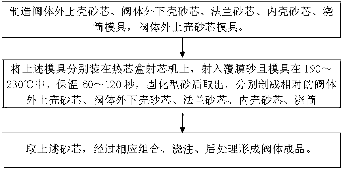
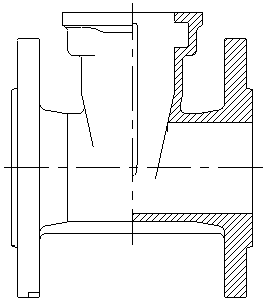
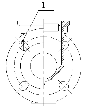
[0032] see figure 1 , the present invention provides a combined pouring process for casting bolt hole gate valve body with flanges through the combination of sand cores of different structures, which improves product quality and production efficiency, saves production costs, and simplifies the manufacturing technology of products. Requirements; the specific process is as follows:

[0033] (1) Manufacture the sand core of the upper shell of the valve body, the sand core of the lower shell of the valve body, the sand core of the flange, the sand core of the inner shell, and the casting mold, and the sand core mold of the upper shell of the valve body is used to form the sand core 2 of the upper shell of the valve body, The sand core mold for the va...


PUM


Abstract

The invention discloses a valve body combined casting process for a sluice valve with flange casting with bolt hole. The process comprises steps of: first preparing a mold of an upper shell core outside the valve body, a mold of a lower shell outside the valve body, a flange core mold, an inner shell core mold, a casting cylinder mold and a mold of an upper core mould outside the valve body; respectively arranging the above molds on a hot box core shooter, injecting precoated sand and insulating the molds at 190-230 DEG C for 60-120 s, curing the casting sand, taking out, and respectively preparing into an upper shell core outside the valve body, a lower shell core outside the valve body, a flange core, an inner shell core and a casting cylinder; and finally conducting corresponding combination, casting and post treatment on the above cores to form a valve body product. The valve body produced by the above process has advantages of tightly matched and fixed components, good surface smoothness, high shape size precision, and no back-end production processing procedure; meanwhile, in the production process, procedure preparation is conducted by using cores of different shapes, so as to facilitate collaboration production by many people, improve production efficiency and save production cost. Therefore, the invention creates a novel pattern for casting process.

Description

technical field [0001] The invention relates to a casting process for a valve body, in particular to a combined casting process for a valve body of a directly cast bolt hole gate valve with a flange. Background technique [0002] At present, the general casting process of gate valve body has at least one pair of structural molds forming the outer shape of the valve body and one pair of core box molds forming the inner cavity of the valve body. Inner cavity, there are no bolt holes on the finished flange of the valve body casting made in this way, these bolt holes need to be drilled, which not only affects the production capacity, but also the accuracy of the bolt holes cannot be guaranteed; A pair of core box molds to form the inner cavity of the valve, a pair of sand core molds to form the flange bolt hole convex column structure, the shape mold forms the outer contour of the valve body, the core box forms the inner hole of the valve body, and the sand core with the flange ...

Claims


Application Information

Patent Timeline
IPC IPC(8): B22C9/24
Inventor 孙述全
Owner WUHU JINMAO FLUID TECH CO LTD
Why Eureka
Try Eureka