
Interferometry measurement system of micro-displacement based on cat eye reflecting principle
A measurement system and micro-displacement technology, applied in the field of geometric quantity measurement, can solve problems such as unsuitable use of corner prisms, and achieve the effect of solving the problem of high-accuracy non-contact micro-displacement measurement, easy implementation, and high measurement resolution
- Summary
- Abstract
- Description
- Claims
- Application Information
AI Technical Summary
Problems solved by technology
Method used
Image

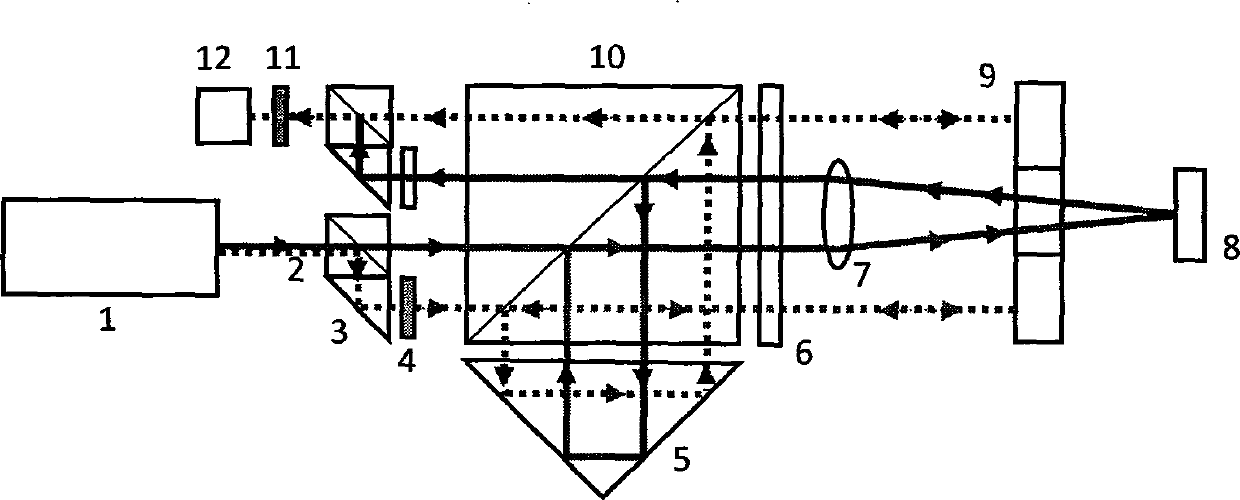


Examples
Embodiment 1
[0026] An interference micro-displacement measurement system based on the cat's eye reflection principle of the present invention, comprising: a frequency-stabilized laser light source 1, a small polarizing beam splitter 2, a right-angle prism 3, a half-wave plate 4, a corner cube prism 5, and a quarter-wave plate 6 , lens 7, plane mirror 9, large polarizing beam splitter 10, polarizer 11 and photoelectric receiver 12, such as figure 1 shown;
[0027] Taking the large polarizing beam splitter 10 as the center, explain the positional relationship between the various components of the system;
[0028] The left side of the large polarizing beam splitter 10 is a combination of two groups of small polarizing beam splitters 2 and rectangular prisms 3 placed side by side up and down. The small polarizing beam splitters 2 and rectangular prisms 3 are glued together or placed close to each other. The total of the two groups of mirrors The width is approximately equal to the width of t...
PUM
 Abstract
Description
Claims
Application Information