
Pairing bearing vibration signal collection device

A bearing vibration and signal acquisition technology, applied in the direction of electrical devices, measuring devices, instruments, etc., can solve the problems of increased difficulty in manufacturing and assembly, interference and difficulty in signal processing and stripping analysis, complex structure of signal acquisition devices, etc., to achieve Convenient processing and assembly, small size, and the effect of avoiding interference

Active Publication Date: 2013-05-15
NO 510 INST THE FIFTH RES INST OFCHINA AEROSPAE SCI & TECH
View PDF3 Cites 4 Cited by
  • Summary
  • Abstract
  • Description
  • Claims
  • Application Information

AI Technical Summary

Problems solved by technology

[0003] The existing vibration signal acquisition device for rolling ball bearings adopts a complex transmission system, and an array of support bearings is usually used in the transmission shaft system. When the acceleration sensor collects the vibration signal of the test bearing, the vibration signal of the support bearing in the transmission shaft system It is transmitted to the test bearing and mixed with the vibration signal of the test bearing in the same test frequency spectrum, causing certain interference and difficulty to the subsequent signal processing and peeling analysis
At the same time, the existing rolling ball bearing vibration signal acquisition device uses a relatively complicated loading mechanism to load the test bearing, which makes the structure of the entire signal acquisition device complex, and the difficulty of manufacturing and assembly increases

Method used


Image

  • Pairing bearing vibration signal collection device
  • Pairing bearing vibration signal collection device

Examples


Embodiment Construction

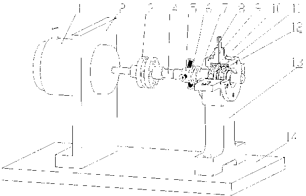
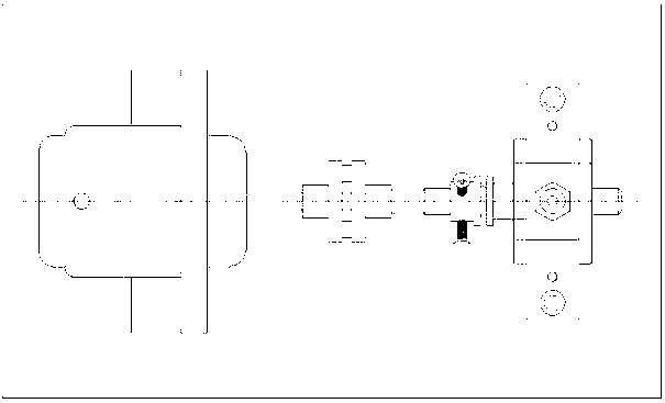
[0014] Such as Figure 1-2 As shown, the bearing signal acquisition device is mainly composed of a motor 1, a motor support 2, a coupling 3, a main shaft 4, a locking ring 5, a locking screw 6, a loading spacer I7, a bearing cover 8, an acceleration sensor 9, a bearing 10 and a bearing 12, two bearings are fixed on the same set of bearings 13.

[0015] The weight used to load the axial force is loaded on the loading spacer I7, the main shaft 4 rotates, and drives the locking ring 5 and the loading spacer I7, and the loading spacer I7 has a pressing force on the inner ring of the bearing 10, which is blocked by the bearing cap Effect, exert axial force on the bearing. Since there is also a loading spacer II11 between the two bearings, and the loading spacer II11 is tightly engaged with the outer rings of the two bearings, so when the loading spacer I7 exerts an axial force on the bearing 10, the bearing 12 will also be subjected to the same force. axial force.

[0016] The d...


PUM


Abstract

The invention discloses a pairing bearing vibration signal collection device which comprises a motor, a motor support seat, a coupler, a main shaft, a locking ring, a locking screw, a loading space ring and two sets of bearings. The motor is fixed on the motor support seat. A motor shaft is connected on the main shaft through the coupler. The main shaft is provided with the locking ring with a connecting flange. The locking ring is provided with the locking screw which is capable of tightly locking the locking ring on the main shaft. The main shaft is further provided with the loading space ring I which is provided with a flange, the flange is opposite to and connected with the flange of the locking ring. The two sets of bearings support the main shaft and are fixed on the same bearing seat. The loading space ring I relatively contacts a bearing inner ring of the loading space ring. The motor support seat and the bearing seat are fixed on the same base seat. Axial loading force of the pairing bearing vibration signal collection device is loaded on the loading pace ring I. The pairing bearing vibration signal collection device effectively avoids interference on vibration signal collection, and the interference is caused by utilizing a plurality of support bearings. The pairing bearing vibration signal collection device has the advantages of being simple in structure and design, small in size, convenient to process and assemble and the like.

Description

technical field [0001] The invention relates to a paired bearing vibration signal acquisition device, which belongs to the technical field of rolling ball bearing testing. Background technique [0002] The vibration signal is an important index to characterize the operating characteristics of the bearing. Analyzing and in-depth research on the vibration characteristics of rolling ball bearings under specific rotational speed and axial load is an important research method for evaluating the quality and operating state of bearings. [0003] The existing vibration signal acquisition device for rolling ball bearings adopts a complex transmission system, and an array of support bearings is usually used in the transmission shaft system. When the acceleration sensor collects the vibration signal of the test bearing, the vibration signal of the support bearing in the transmission shaft system It is transmitted to the test bearing and mixed with the vibration signal of the test bear...

Claims


Application Information

Patent Timeline
IPC IPC(8): G01H11/06
Inventor 张凯锋周晖胡继星桑瑞鹏胡汉军王叙博
Owner NO 510 INST THE FIFTH RES INST OFCHINA AEROSPAE SCI & TECH
Learn More