
Clamping control method of three-jaw small roller centering fixture

A control method and centering fixture technology, applied in the direction of the chuck, etc., can solve the problems of restricting the application of the three-jaw small roller centering fixture, complex structure, high cost, etc., achieving simple method, less manual participation, avoiding formula Deduced effect

Inactive Publication Date: 2013-05-22
SOUTHEAST UNIV
View PDF2 Cites 1 Cited by
  • Summary
  • Abstract
  • Description
  • Claims
  • Application Information

AI Technical Summary

Problems solved by technology

Although the overall structure of the three-jaw small roller centering fixture is simple, the clamping control part of the most important part has always been the difficulty of the fixture, which is also one of the main reasons that limit the wide application of the three-jaw small roller centering fixture. The control method of the three-jaw small roller centering fixture has been proposed by researchers to be hydraulic control and servo control. Although this control method can achieve no error in principle and achieve zero error control in the simulation, the structure of this control method Complexity and high cost greatly limit the application of three-jaw small roller centering fixtures

Method used


Image

  • Clamping control method of three-jaw small roller centering fixture
  • Clamping control method of three-jaw small roller centering fixture
  • Clamping control method of three-jaw small roller centering fixture

Examples


Embodiment Construction

[0024] In order to make the above features and methods of the present invention more comprehensible, the invention will be further described below with reference to the accompanying drawings and an example.

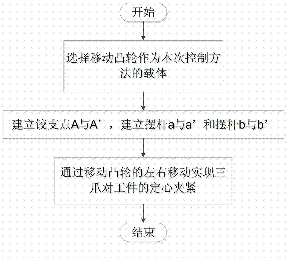
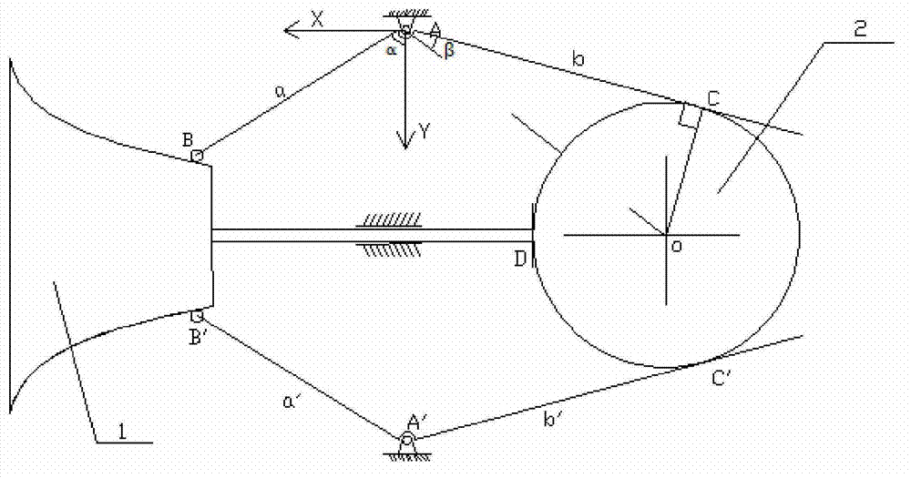
[0025] Such as figure 1 As shown, it is a schematic flow chart of the structural structure of the three-jaw small roller centering fixture of the present invention, combined with image 3 Schematic diagram of the structure of the three-jaw small roller centering fixture. This feature mainly includes the following steps:

[0026] In step 1, the horizontally moving cam 1 is selected as the carrier of the clamping control method. When the clamp is in the initial position, one end of the cam is in contact with the workpiece 2 at the contact point D,

[0027] The fixture described in step 2 is set up using the following method:

[0028] Along the axis of the moving cam as the center line, establish the hinge point A and the hinge point A' in the main section, and the hinge p...


PUM


Abstract

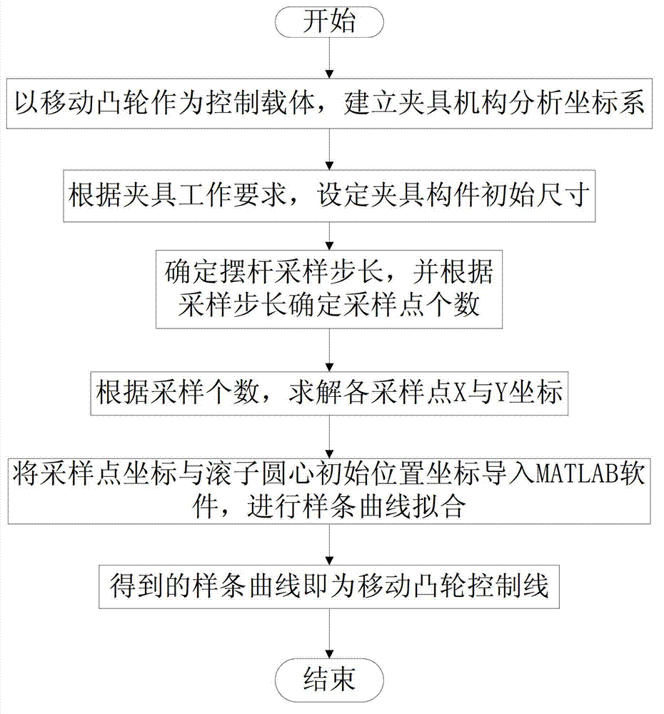
The invention discloses a clamping control method of a three-jaw small roller centering fixture. A cam is selected as a carrier of the control method of the three-jaw small roller centering fixture. The operating principle of the control method is that clamping operations of the fixture are achieved by utilizing axial movement of the translating cam and through a control line, wherein the control line is obtained through the following steps: analysis coordinates are built, the variable quantity of an included angle of a swing rod a and a Y axis is used as a sampling step length, the circle center position of a roller B is used as a sampling point, the sampling amount is confirmed, X axis and Y axis coordinates of the sampling point are obtained according to the sampling amount, the obtained sampling coordinates is leaded into a matrix laboratory (MATLAB) to conduct spline curve fitting, and the obtained spline curve fitting is the control line of the translating cam. A sampling interpolating solving method id adopted by the control method, and therefore massive formula derivation is avoided, and because interpolating calculation part is procedurally processed by MATLAB software, the manpower participation amount is small, and the method is easy and convenient to use, and fast.

Description

technical field [0001] The invention belongs to the technical field of design of an automatic centering fixture in the mechanical manufacturing process, and in particular relates to a clamping control method of a three-jaw small roller centering fixture. Background technique [0002] At present, there are many types of automatic centering fixtures in China, among which the three-jaw small roller centering fixture introduced in the present invention is a relatively novel structure among automatic centering fixtures, especially for shaft parts with large changes in outer diameter. It has very good application effect. Although the overall structure of the three-jaw small roller centering fixture is simple, the clamping control part of the most important part has always been the difficulty of the fixture, which is also one of the main reasons that limit the wide application of the three-jaw small roller centering fixture. For the control method of the three-jaw small roller cen...

Claims


Application Information

Patent Timeline
IPC IPC(8): B23B31/24
Inventor 汤文成徐楠楠徐冬黄辉祥
Owner SOUTHEAST UNIV
Learn More