Electric system tide optimization method for high-efficient processing complex electric control appliance

A technology of power control and optimization method, which is applied in the direction of electrical components, circuit devices, AC network circuits, etc., can solve problems such as insufficient program flexibility and scalability, difficulty in derivation and implementation, and complex calculation formulas, so as to improve maintainability , avoid formula derivation and implementation, and improve the effect of calculation accuracy

Inactive Publication Date: 2011-03-30
ZHEJIANG UNIV
View PDF0 Cites 0 Cited by
  • Summary
  • Abstract
  • Description
  • Claims
  • Application Information

AI Technical Summary

Problems solved by technology

However, the calculation formulas of injected power and internal constraints corresponding to complex power control equipment such as FACTS and HVDC are usually complex and show strong nonlinearity, which makes the corresponding first-order and second-order derivative calculation formulas complicated and difficult to derive and implement.
Therefore, the methods proposed in the above literatures all have the disadvantages of complex implementation, insufficient program flexibility and scalability, and poor maintainability.

Method used


Image

  • Electric system tide optimization method for high-efficient processing complex electric control appliance
  • Electric system tide optimization method for high-efficient processing complex electric control appliance
  • Electric system tide optimization method for high-efficient processing complex electric control appliance

Examples


Embodiment 1

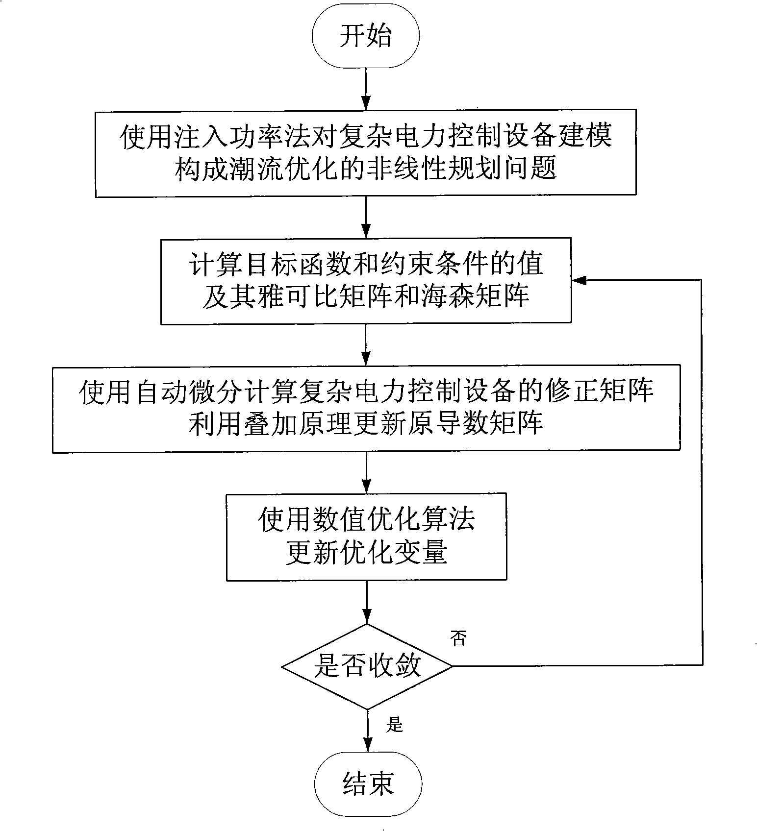
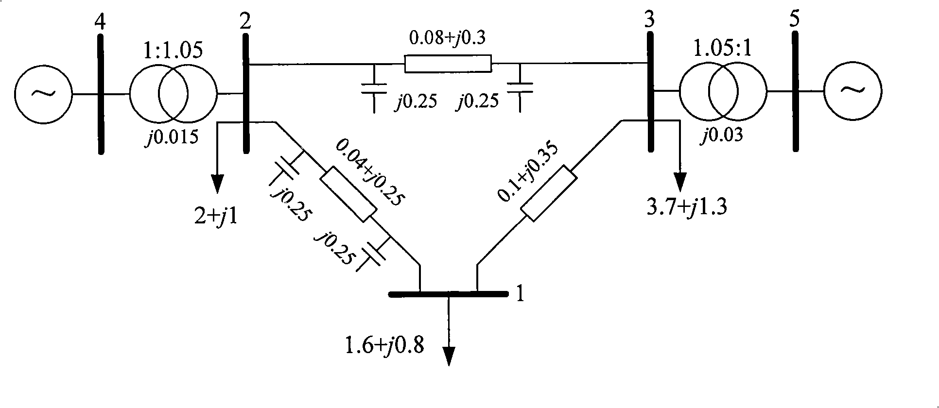
[0052] consider as figure 2 In the example power system shown, if other complex power control devices are not considered, the steps of power flow optimization using the interior point method are as follows:

[0053] Calculate the grid admittance matrix (the results are omitted), and set the optimization variable of the power flow optimization problem as x, which includes [P G , Q G , V e , V f , X c ], where P G and Q G are the active output and reactive output of the generator respectively, V e and V f are the real and imaginary parts of the voltage at each node, X c Customize the control variables of the model for other users in the system.

[0054] The objective function is set as the minimum fuel cost of system power generation (1), where α is the economic coefficient of each generator.

[0055] f ( x ) = Σ ( α i 2 ...

Embodiment 2

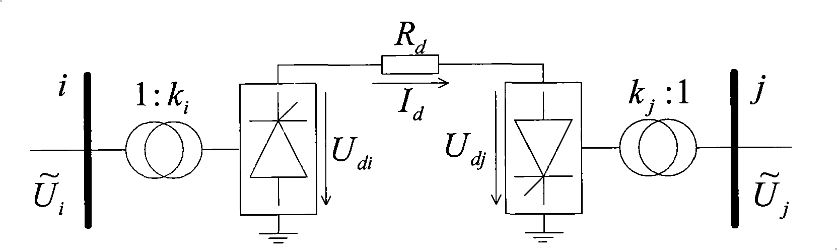
[0106] This embodiment uses the same objective function, constraints and numerical optimization algorithm as in Embodiment 1, and considers multiple groups of test power systems as shown in Table 3, which involve static var compensators (Static Var Compensators, SVC) and Thyristor Controlled Series Capacitor (TCSC) are three complex power control devices.

[0107] Table 3 Summary of Test System

[0108]

[0109] In order to compare the performance of the method proposed by the present invention, the following two reference methods are set for comparison.

[0110] 1. Manual programming: the correction matrix of complex power control equipment is realized by manual programming;

[0111] 2. Automatic differentiation: All Jacobian matrices and Hessian matrices are calculated using automatic differentiation.

[0112] Table 4 shows the calculation efficiency comparison between the method proposed by the present invention and the above two groups of comparison methods.

[0113]...


PUM


Abstract

The invention discloses a power system flow optimization method for effectively processing a complex electric power control device. The method adopts a node power injection method for modeling for the electric power control device, performs processing to the device and enables the device to be integrated to the traditional flow optimization by using a superposition principle, and effectively calculates the corrected matrixes of the Jacobian matrix and the Hessenberg matrix of the electric power control device to the objective function and the constraint condition by using an automatic differentiation technology. The method is efficient, flexible and feasible, keeps the high efficiency of the traditional flow optimization procedure, protects the existing code investment, can extend to other user-defined models and meets the requirements of analysis, running and planning of the modern power system.

Description

technical field [0001] The invention belongs to the technical field of power system operation, analysis and scheduling, and in particular relates to a power system power flow optimization method for efficiently processing complex power control equipment. Background technique [0002] In recent years, with the continuous development of power electronics technology, complex power control equipment represented by Flexible AC Transmission System (FACTS) and High Voltage Direct Current (HVDC) has been widely used in modern power systems Among them, compared with traditional AC transmission methods, FACTS and HVDC have many advantages such as increasing transmission capacity, suppressing power flow oscillation, reducing line loss, and facilitating power flow control. The emergence of these new types of complex power control equipment makes it possible for modern grid power remote transmission, flexible power flow adjustment, and dynamic reactive power compensation. At the same tim...

Claims


Application Information

Patent Timeline
Patent Type & Authority Patents(China)
IPC IPC(8): H02J3/00
Inventor 江全元耿光超张国宏
Owner ZHEJIANG UNIV
Why Eureka
Try Eureka