
Tidal current energy power generation device capable of being used in low-speed environment

A power generation device and technology of tidal current energy, which is applied in the field of tidal current energy power generation devices, can solve problems such as inability to realize effective utilization of tidal current energy, and achieve the effects of improving energy utilization rate, increasing stability and reliability

Inactive Publication Date: 2013-05-22
XIAMEN UNIV
View PDF11 Cites 14 Cited by
  • Summary
  • Abstract
  • Description
  • Claims
  • Application Information

AI Technical Summary

Problems solved by technology

[0004] As far as my country is concerned, although the tidal energy is abundant overall and the coastline is long, there are relatively few areas with a tidal velocity greater than 1m / s. Because the tidal velocity is too low, most areas cannot realize the effective use of tidal energy. Therefore, in order to realize the extensive and efficient utilization of tidal current energy, the key lies in the efficient collection and utilization of tidal current energy in a large area with low flow velocity. Practical significance

Method used


Image

  • Tidal current energy power generation device capable of being used in low-speed environment
  • Tidal current energy power generation device capable of being used in low-speed environment
  • Tidal current energy power generation device capable of being used in low-speed environment

Examples


Embodiment Construction

[0024] In order to better understand the present invention, the following embodiments will further illustrate the present invention in conjunction with the accompanying drawings.

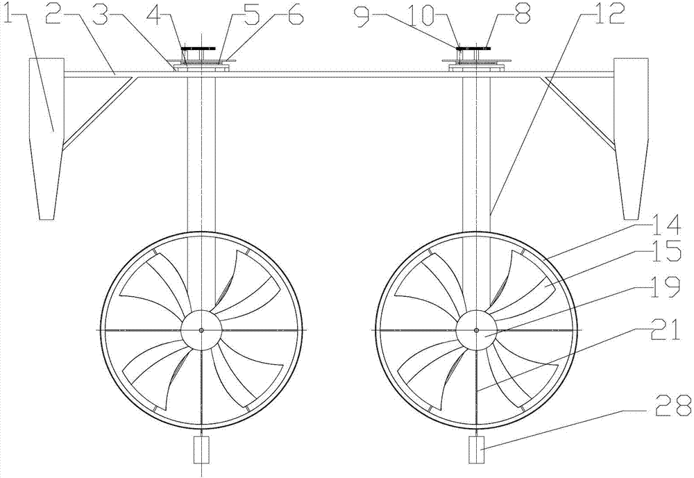
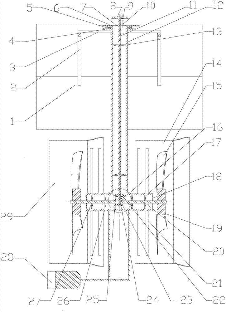
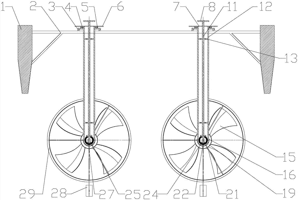
[0025] see Figure 1~4 , the embodiment of the present invention is provided with a main frame, an energy collection and conversion device and a speed-up transmission mechanism.

[0026] The main frame is mainly composed of a floating block 1, a floating block supporting rib 2, a supporting beam 3, a working platform 4, a slewing bearing 5, a supporting plate 6, a main shaft waterproof pipe 12, a blade shaft waterproof pipe 27 and some related components. The two floating blocks on the left and right are connected by two floating block support ribs 2. The floating blocks are supported by a support beam 3 on the shelf. A working device. The working platform 4 is threadedly connected to the lower end of the slewing bearing 5, and the upper end of the slewing bearing 5 is connected to the support pla...


PUM


Abstract

The invention discloses a tidal current energy power generation device capable of being used in a low-speed environment and relates to a tidal current energy power generation device. A main body frame, an energy collection and conversion device and a speed-up drive mechanism are arranged. The main body frame is provided with floating blocks, floating block support ribs, supporting beams, working platforms, slewing supporting bearings, supporting plates, a main shaft waterproof pipeline and a leaf blade shaft waterproof pipeline in an erecting mode. The energy collection and conversion device is provided with a front rectification cover, a rear rectification cover, a guide plate, hydraulic turbine blades and an electric generator. The speed-up drive mechanism is provided with a main shaft, a front leaf blade shaft, a rear leaf blade shaft, a main shaft upper bevel gear, a main shaft lower bevel gear, a front leaf blade shaft bevel gear and a rear leaf blade shaft bevel gear. Fluid mechanics knowledge is fully used, a rectification cover structure is used for carrying out rectification and acceleration to low-speed tidal current flowing through the leaf blades, a low-speed tidal current sea area is enabled to be suitable for carrying out power generation, meanwhile, leaf blade ways which are identical in direction and a guide vane structure are adopted, tidal current flowing through the power generation device is enabled to achieve high-efficiency conversion, and the tidal current energy power generation device capable of being used in the low-speed environment is especially suitable for carrying out high-efficiency conversion to the low-speed tidal current.

Description

technical field [0001] The invention relates to a tidal current energy generating device, in particular to a tidal current energy generating device which can be used in a low-speed environment. Background technique [0002] Tidal current energy refers to the kinetic energy (velocity head) contained in the tidal water when it moves horizontally. Tidal current energy is a clean and non-polluting energy with huge reserves, inexhaustible supply, and inexhaustible use. Under the background of energy shortage in the world today, its collection and utilization have very important strategic significance. [0003] The utilization method of tidal current energy is mainly power generation, and its principle is similar to that of wind power generation, but because the energy flow density of tidal current energy is several times larger than that of wind energy, and compared with wave energy and wind energy, the flow velocity is stable and regular, and can be used The space is large. Ti...

Claims


Application Information

Patent Timeline
Patent Type & Authority Applications(China)
IPC IPC(8): F03B13/26F03B3/18F03B3/12F03B15/06F16H1/22
CPCY02E10/223Y02E10/28Y02E10/20Y02E10/30
Inventor 鲍锋杨锦文何意
Owner XIAMEN UNIV
Learn More