Filtering type wavelength tunable external cavity laser

A technology of lasers and wavelengths, applied in lasers, laser components, phonon exciters, etc., can solve the problems of high cost and achieve low cost, low insertion loss, and compact structure

Active Publication Date: 2013-05-22
INST OF SEMICONDUCTORS - CHINESE ACAD OF SCI
View PDF6 Cites 9 Cited by
  • Summary
  • Abstract
  • Description
  • Claims
  • Application Information

AI Technical Summary

Problems solved by technology

[0003] At present, most of the light sources in the DWDM system use fixed-wavelength DFB lasers, which means that to increase the number of channels in the DWDM system can only be produced by making many DFB lasers with different output wavelengths. Considering the related inventory and spare , it will be very expensive

Method used


Image

  • Filtering type wavelength tunable external cavity laser
  • Filtering type wavelength tunable external cavity laser
  • Filtering type wavelength tunable external cavity laser

Examples


Embodiment 1

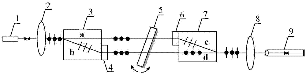
[0019] figure 1 It shows the composition structure of the filter-type wavelength tunable external cavity laser in the preferred embodiment of the present invention, such as figure 1 As shown, the laser includes a broadband light source 1 , a collimating lens 2 , birefringent elements 3 and 7 , half-wave plates 4 and 6 , an interference filter 5 , a converging lens 8 and an optical fiber 9 .

[0020] The broadband light source 1 is an unpackaged quantum dot or quantum well superluminescent light-emitting diode (SLD) device, and its rear cavity surface is located at the focus of the collimator lens 2 for system coupling, and its front cavity surface is used as the output of the entire system. The light emitted by the broadband light source is collimated by the collimator lens 2 and becomes parallel light; when the parallel light is incident on the birefringent element 3 again, two beams of linearly polarized light a with the same frequency are generated due to the optical anisot...

Embodiment 2

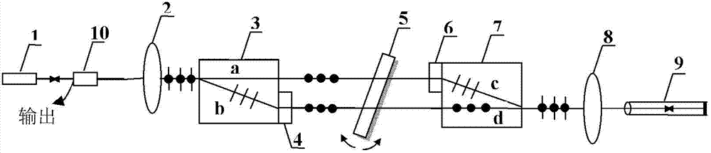
[0024] figure 2 A schematic structural diagram of a filter-type wavelength-tunable external cavity laser in another preferred embodiment of the present invention is shown.

[0025] Such as figure 2 As shown, the laser includes: broadband light source 1, collimating lens 2, birefringent elements 3 and 7, half-wave plates 4 and 6, interference filter 5, converging lens 8, single-mode fiber 9 and 1×2 type fiber Coupler 10. The composition of the system is basically the same as that in Embodiment 1, except that the broadband light source can use a packaged SLD device. Since it only outputs through a pigtail and is used for coupling with the birefringent element, the laser A 1×2 fiber optic coupler is added to it, which can realize optical combination / splitting. There are two optical fiber splits at the left end, and one optical fiber at the right. One of the two optical fiber splits at the left end is the same as the packaged The output pigtail of the SLD device is connected ...


PUM


Abstract

The invention discloses a filtering type wavelength tunable external cavity laser. The filtering type wavelength tunable external cavity laser can randomly control laser wavelength within a certain wavelength range and comprises a broadband light source, a collimating lens, a first birefringence element, a second birefringence element, a first half wave plate, a second half wave plate, an interference filter, a convergent lens and an optical fiber. A superradiance luminescent tube comprises the broadband light source, light emitted by the light source is collimated by the collimating lens and then spotted on the interference filter through the first birefringence element and the first half wave plate respectively, and light transmitting the interference filter passes through the second half wave plate and the second birefringence element and then focused and coupled through the convergent lens to the optical fiber; and the tail end of the optical fiber is plated with reflecting films to enable light to return along the original way. The filtering type wavelength tunable external cavity laser is low in cost, compact in structure, high in temperature stability and simple in operation, and can finally achieve laser wavelength continuous tuning within the certain wavelength range.

Description

technical field [0001] The invention relates to the technical fields of optical fiber sensing and optoelectronics, in particular to a filter type wavelength tunable external cavity laser whose output lasing wavelength can be continuously changed. Background technique [0002] Wavelength tunable lasers can control the lasing wavelength arbitrarily within a certain wavelength range, and are widely used in optical fiber communication, spectrum testing, biomedicine and atmospheric monitoring, etc. The establishment of multiplexing (WDM) technology and dense wavelength division multiplexing (DWDM) technology requires precise output wavelength of the light source, high stability, and narrow laser line width. If a semiconductor laser with a large wavelength tuning range is selected to expand the channel number of the DWDM system, the number of fixed-frequency lasers is effectively reduced, cost is saved, and various innovative and flexible designs are realized. [0003] At present...

Claims


Application Information

Patent Timeline
Patent Type & Authority Applications(China)
IPC IPC(8): H01S3/08H01S3/0941
Inventor 魏恒金鹏王占国
Owner INST OF SEMICONDUCTORS - CHINESE ACAD OF SCI
Why Eureka
Try Eureka