Architecture for a non-lubricated turboshaft engine
A turbine engine and turbine shaft technology, applied in the direction of engine lubrication, turbine/propulsion device lubrication, engine components, etc., can solve problems such as expensive, polluting, and heavy lubrication systems
- Summary
- Abstract
- Description
- Claims
- Application Information
AI Technical Summary
Problems solved by technology
Method used
Image

Examples
Embodiment Construction
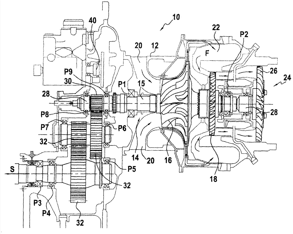
[0039] FIG. 1 is a longitudinal cross-sectional view of a prior art helicopter turboshaft engine 10 . The turboshaft engine 10 includes a casing 12 that houses a gas generator 14 . The gas generator has a gas generator shaft 15 which carries a compressor wheel 16 and a high pressure turbine 18 . Fresh air enters the turboshaft engine through air inlet 20 . The fresh air is then compressed by the compressor 16 before being fed into the combustion chamber 22 where the compressed air is mixed with fuel. Combustion of the mixture of compressed air and fuel produces airflow F that drives rotation of high pressure turbine 18 , which in turn drives compressor 16 . The gas generator is carried by bearings P1 and P2 which provide rotational guidance and absorb the forces experienced by the gas generator 15 . These bearings are lubricated with oil by means of a lubrication system (not shown in the figures). In addition, the turboshaft engine also has a free turbine 24 with a low pre...
PUM
 Abstract
Description
Claims
Application Information
 - R&D
- Intellectual Property
- Life Sciences
- Materials
- Tech Scout
- Unparalleled Data Quality
- Higher Quality Content
- 60% Fewer Hallucinations
Browse by: Latest US Patents, China's latest patents, Technical Efficacy Thesaurus, Application Domain, Technology Topic, Popular Technical Reports.
© 2025 PatSnap. All rights reserved.Legal|Privacy policy|Modern Slavery Act Transparency Statement|Sitemap|About US| Contact US: help@patsnap.com