Handle forming mechanism

A formwork and state technology, applied to other home appliances, home appliances, applications, etc., can solve the problems of no reference value for processing handles, unfavorable mass and rapid production, and unsuitable metal wire handles, etc., to save labor resources , easy operation and maintenance, and the effect of reducing manpower input

Inactive Publication Date: 2014-12-24
上海金熟新材料科技股份有限公司
View PDF6 Cites 0 Cited by
  • Summary
  • Abstract
  • Description
  • Claims
  • Application Information

AI Technical Summary

Problems solved by technology

For this reason, the applicant has searched the literature, and the Chinese Patent Authorization Announcement No. CN101536878B recommends "handles for household appliances and their production molds and production methods". The metal wire handle has no reference significance, especially because only one handle can be formed at a time, so the efficiency is low, which is not conducive to industrialized mass production; and the authorized announcement number CN202174179U provides a Progressive mold", the patent structure is complex and has a specific pertinence that can only form the handle of the pot lid, so it has no enlightening significance for the forming of the metal wire handle; "Mold", the patent can embody the advantages described in columns 0015 to 0019 of the specification, and form a U-shaped workpiece at one time (the patent indicates which occasion the workpiece is used for), but it is not suitable for the forming of metal wire handles Applicable, and because only one U-shaped workpiece can be obtained at a time, the efficiency is low; also, the authorized announcement number CN202199698U discloses a "bending device for single pressing and multi-bending". This patent solution can be applied to bending steel wires, but There is no reference value for processing handles, and the same can only obtain one workpiece at a time, so the efficiency is low; moreover, the "net reinforcement automatic bending forming machine" announced by the publication number CN102172738A, the "net sheet automatic bending forming machine" announced by CN102172739A machine" and CN102172740A disclosed "mesh bar automatic bending machine" are aimed at commercial facilities such as self-selected supermarkets, shopping malls equipped with temporary use of trolleys and shopping baskets for customers when shopping, etc.

Method used


Image

  • Handle forming mechanism
  • Handle forming mechanism

Examples


Embodiment Construction

[0021] In order to enable the examiners of the patent office, especially the public, to understand the technical essence and beneficial effects of the present invention more clearly, the applicant will describe in detail the following in the form of examples, but none of the descriptions to the examples is an explanation of the solutions of the present invention. Any equivalent transformation made according to the concept of the present invention which is merely formal but not substantive shall be regarded as the scope of the technical solution of the present invention.

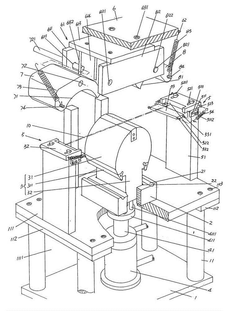
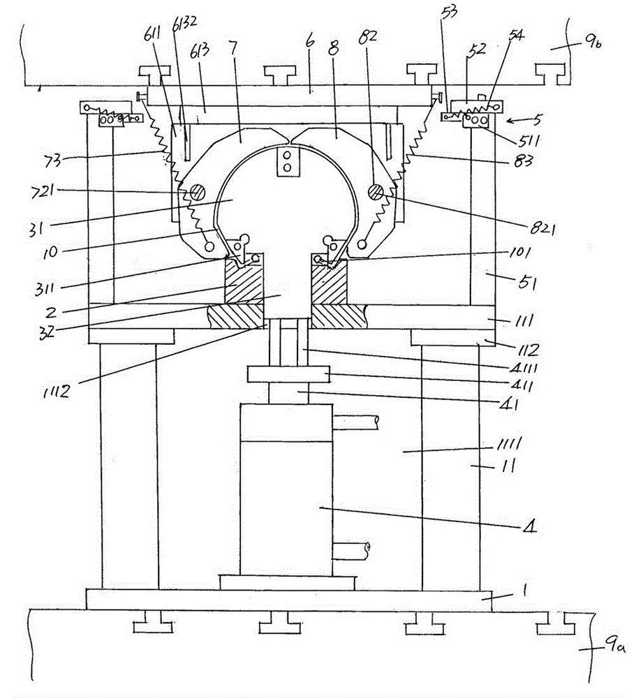
[0022] See figure 1 with figure 2 , a base 1 is given. According to common knowledge, the base 1 is fixed with the working platform of the hydraulic press in use, specifically, with the hydraulic press base 9a of the hydraulic press ( figure 2 Shown) fixed, that is, configured to the hydraulic press base 9a. The hydraulic press mentioned here is preferably but not limited to a Y32-305 hydraulic pre...


PUM


Abstract

The invention discloses a handle forming mechanism and belongs to the technical field of metal wire bending and forming machinery. The handle forming mechanism comprises a base, a mold head seat, an action vat, a pair of wire laying devices and an upper mold frame. A stand column set is fixed at one side of the base. A lower mold frame is fixed on the top of the stand column set, and an allowance cavity is arranged in the middle of the lower mold frame. The mold head seat is fixed with one side of the lower mold frame, a handle foot forming groove is arranged in the upper surface of the mold head seat, and a mold handle matching cavity is arranged in the middle of the mold head seat. A mold head is composed of a semi-cylinder body and a mold handle, handle foot forming molds are respectively arranged at two sides of the semi-cylinder, and the mold handle is arranged at one side of the semi-cylinder body. The action vat is fixed on the base. The pair of wire laying devices is arranged at two sides facing upwards of the lower mold frame. A holding arm frame is fixed on the upper mold frame, a first holding arm is connected at one other end of the holding arm frame, and one side of the first holding arm is provided with a first holding arm arc cavity. A second holding arm is connected at the other end of the holding arm frame, and one side of the second holding arm is provided with a second holding arm arc cavity. Operation intensity is relieved, efficiency is improved, handle quality is ensured, and operation and maintenance are convenient.

Description

technical field [0001] The invention belongs to the technical field of metal wire bending and forming machinery, and in particular relates to a handle forming mechanism for forming containers such as paint buckets, paint buckets, paint buckets, and buckets for daily life. Handle made of metal wire. Background technique [0002] As we all know, the containers not limited to those listed above are all equipped with metal wire handles for gripping and carrying. The structure of this handle seems simple, but in order to meet the strength and corresponding mechanical requirements, the shape of the handle It is rather special, specifically manifested in the fact that there are many inflection points and / or arc transition points, and the requirements for the forming process are relatively strict. In addition, since the handle is a non-standard product, it is not possible to obtain special forming equipment from commercial channels. [0003] At present, most of the above-mentioned...

Claims


Application Information

Patent Timeline
Patent Type & Authority Patents(China)
IPC IPC(8): B21F45/00B21F1/00
Inventor 朱惠琴
Owner 上海金熟新材料科技股份有限公司
Why Eureka
Try Eureka