Semi-independent rear suspension of automobile torsion beam

A torsion beam, semi-independent technology, applied in the direction of suspension, elastic suspension, vehicle components, etc., can solve the problems of waste of cost and time, complex force of torsion bar, high maintenance cost, etc., to avoid desoldering, simple processing, The effect of guaranteeing the life of the stent

Inactive Publication Date: 2013-05-29
柳州孔辉汽车科技有限公司
View PDF7 Cites 12 Cited by
  • Summary
  • Abstract
  • Description
  • Claims
  • Application Information

AI Technical Summary

Problems solved by technology

[0004] 1) After the structure of the torsion beam semi-independent rear suspension is generally determined, the roll stiffness of the torsion beam semi-independent rear suspension is usually adjusted by changing the diameter of the torsion bar, so as to achieve the required vehicle handling performance, but because the torsion bar directly Welded on the torsion beam, if the roll stiffness of the torsion beam is changed, the torsion beam must be replaced as a whole, which wastes cost and time
[0005] 2) During the road test, in order to ensure safety, the general design is that the torsion bar breaks first. Since the torsion bar is welded to the torsion beam, after the torsion bar breaks, the torsion beam needs to be replaced as a whole, and the maintenance cost is high
[0006] 3) During the driving process of the car, due to the relatively long torsion bar, the force of the torsion bar is complicated, and it is easy to desolder, break and vibrate

Method used


Image

  • Semi-independent rear suspension of automobile torsion beam
  • Semi-independent rear suspension of automobile torsion beam
  • Semi-independent rear suspension of automobile torsion beam

Examples


Embodiment Construction

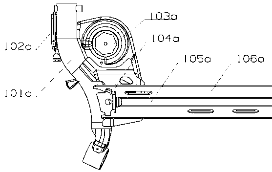
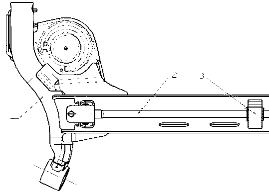
[0032] An automobile torsion beam semi-independent rear suspension, such as figure 2 As shown, the semi-independent rear suspension of the automobile torsion beam is a detachable structure, including a torsion beam welded part 1, a torsion bar welded part 2 and a torsion bar stabilizer 3;

[0033] The torsion beam welded part 1 includes a beam 105, a longitudinal arm 101 at both ends of the beam, a hub bracket 102, and a spring seat 103. The ends of the two ends of the beam are respectively provided with two holes and connected with a beam reinforcement plate 4. The beam, The longitudinal arms, the wheel hub brackets, the spring seats and the beam reinforcement plates at both ends of the beam are connected into one body by welding, wherein the beam reinforcement plates 104 are fixed with welding nuts;

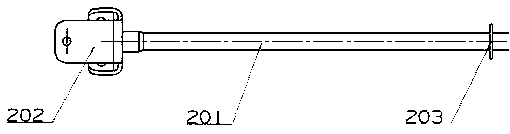
[0034] The torsion bar weldment 2 includes a torsion bar 201, a torsion bar bracket 202 located at both ends of the torsion bar 201 and two pads 203 located in the middle of t...


PUM


Abstract

A semi-independent rear suspension of an automobile torsion beam is in a detachable structure. The semi-independent rear suspension of the automobile torsion beam comprises a torsion beam welded part, a torsion bar welded part and a torsion bar stabilizer, wherein the torsion beam welded part is composed of a trailing arm, a wheel hub support, a spring seat, a horizontal beam and a horizontal beam reinforcing plate, wherein the trailing arm, the wheel hub support, the spring seat, the horizontal beam and the horizontal beam reinforcing plate are welded into one integrated structure. Welded nuts are arranged on the horizontal beam reinforcing plate. The torsion bar welded part comprises a torsion bar, torsion bar supports at two ends of the torsion bar and two cushion discs placed at the middle portion of the torsion bar, wherein the torsion bar, the torsion bar supports and the two cushion discs placed at the middle portion of the torsion bar are connected into one whole through a welding method and two welding nuts are arranged on each torsion bar support. One side of the torsion bar stabilizer is provided with an opening, and the torsion bar stabilizer is clamped between the two cushion discs at the middle portion of the torsion bar through the opening. The torsion bar stabilizer can not move left and right. The torsion bar welded part provided with the torsion bar stabilizer in an assembled mode is installed on the horizontal beam of the torsion beam welded part in a matched mode through the two bolts placed on each torsion bar support and one bolt is installed on the horizontal beam reinforcing plate in a matched mode. The semi-independent rear suspension of the torsion beam is dismountable, so that adjustment of the performance of the torsion beam and the replacement of the quick-wear torsion bar are benefited.

Description

technical field [0001] The invention relates to a vehicle rear independent suspension mechanism, in particular to a detachable automobile torsion beam semi-independent rear suspension. Background technique [0002] The torsion beam semi-independent suspension is a commonly used vehicle rear suspension structure. It has the advantages of simple structure, low cost and small space occupation. The arms are welded together, the front end of the trailing arm is connected with the body through a bushing, the wheel hub bracket welded on the rear end of the trailing arm is connected with the wheel hub, the shock absorber is connected with the trailing arm by bolts, and the spring is installed in the welding on the trailing arm and the torsion beam. between the spring seats. The trailing arm of the torsion beam can swing up and down around the front-end bushing, and the springs transmit various forces and moments between the body and the wheels, which mainly bear the load, ease the ...

Claims


Application Information

Patent Timeline
Patent Type & Authority Applications(China)
IPC IPC(8): B60G3/02B60G11/18
Inventor 赵亮胡少君张宝霞
Owner 柳州孔辉汽车科技有限公司
Why Eureka
Try Eureka