Three-cylinder hot-air engine

A hot gas engine and cylinder technology, applied in hot gas variable displacement engine devices, machines/engines, mechanical equipment, etc., can solve problems such as heat loss and low fuel efficiency

Inactive Publication Date: 2013-05-29
ZEROQ SCI & TECH
View PDF6 Cites 7 Cited by
  • Summary
  • Abstract
  • Description
  • Claims
  • Application Information

AI Technical Summary

Problems solved by technology

[0002] Traditional internal combustion engines generally discharge high-temperature exhaust gas directly, resulting in serious heat loss
However, the gas working medium in the traditional heat engine needs heat to heat, the conventional heating method is external combustion, and the fuel usage efficiency is also low. Therefore, for the fuel efficiency of the existing internal combustion engine and heat engine, it is necessary to provide Engines for further utilization of waste heat from engine exhaust

Method used


Image

  • Three-cylinder hot-air engine
  • Three-cylinder hot-air engine
  • Three-cylinder hot-air engine

Examples


Embodiment 1

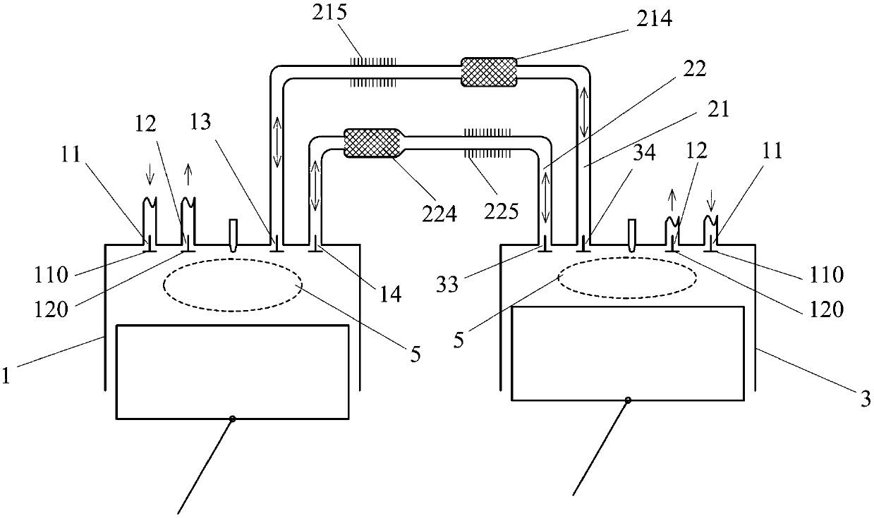
[0092] Such as figure 1 The three types of door hot gas engines shown include two cylinder-piston mechanisms: cylinder-piston mechanism A1 and cylinder-piston mechanism B3, the cylinders of the two cylinder-piston mechanisms are provided with air inlets 11 and exhaust ports 12, and Both cylinder-piston mechanisms are provided with a combustion chamber 5, each of the air inlets 11 is provided with a corresponding intake valve 110, and each of the exhaust ports 12 is provided with a corresponding exhaust valve. Door 120; a reciprocating flow port A13 and a reciprocating flow port B14 are set on the cylinder of the cylinder-piston mechanism A1, a reciprocating flow port C33 and a reciprocating flow port D34 are set on the cylinder of the cylinder-piston mechanism B3, and the reciprocating flow port A13, the reciprocating flow port B14, the reciprocating flow port C33 and the reciprocating flow port D34 are provided with corresponding reciprocating flow control doors, and the rec...

Embodiment 2

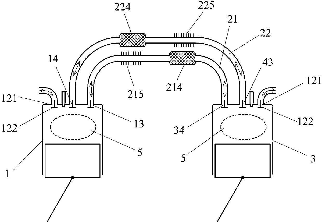
[0095] Such as figure 2 The difference between the shown three-type door hot gas engine and Embodiment 1 is that the air intake port 11 and the exhaust port 12 on the two cylinder-piston mechanisms are integrally arranged as a shared air port 121 for intake and exhaust. , the intake and exhaust common air port 121 is provided with a corresponding intake and exhaust common air valve 122 .

Embodiment 3

[0097] Such as image 3 The difference between the three types of door hot gas engines shown in Embodiment 2 is that: the reciprocating flow port A13 and the reciprocating flow port B14 are integrated into a reciprocating flow port E15, and the reciprocating flow port C33 and the reciprocating flow port C33 The flow port D34 is integrally set as a reciprocating flow port F35, and the reciprocating flow port E15 communicates with one end of the reciprocating communication channel A21 and one end of the reciprocating communication channel B22 through the reciprocating channel 23 at the same time, and the reciprocating flow port F35 passes through the reciprocating channel 23. Another reciprocating passage 23 communicates with the other end of the reciprocating communication passage A21 and the other end of the reciprocating communication passage B22 at the same time; two control valves are respectively arranged on the reciprocating communication passage A21 and the reciprocating ...


PUM


Abstract

The invention discloses a three-cylinder hot-air engine. The three-cylinder hot-air engine comprises two cylinder piston mechanisms, the two cylinder piston mechanisms are provided with air inlets and air outlets, and the two cylinder piston mechanisms are communicated through two reciprocation communication channels. One of the cylinder piston mechanisms in combustion engine burning action stroke is used as a hot cylinder of a Stirling engine, and the other cylinder piston mechanism is used as a cold cylinder of the Stirling engine, wherein gas working media for Stirling circulation are high-temperature gas after burning action stroke. Thus, a combustion engine and the Stirling circulation can be combined organically, and system heat efficiency can be improved greatly.

Description

technical field [0001] The invention relates to the field of thermal power, in particular to a heat engine. Background technique [0002] Traditional internal combustion engines generally discharge high-temperature exhaust gas directly, resulting in serious heat loss. However, the gas working medium in the traditional heat engine needs heat to heat, the conventional heating method is external combustion, and the fuel usage efficiency is also low. Therefore, for the fuel efficiency of the existing internal combustion engine and heat engine, it is necessary to provide a An engine that further utilizes the waste heat from the engine exhaust. Contents of the invention [0003] In order to solve the above problems, the technical scheme proposed by the present invention is as follows: [0004] Scheme 1: A three-type door hot gas engine, including a cylinder-piston mechanism A and a cylinder-piston mechanism B, the cylinders of the cylinder-piston mechanism A and the cylinders ...

Claims


Application Information

Patent Timeline
Patent Type & Authority Applications(China)
IPC IPC(8): F02G1/044F02G1/053F02G1/045
Inventor 靳北彪
Owner ZEROQ SCI & TECH
Why Eureka
Try Eureka