
Hydraulic system for controlling rotation of boom, control method thereof and concrete pumping equipment

A hydraulic system and concrete pump technology, applied in the direction of fluid pressure actuation system safety, fluid pressure actuation system components, mechanical equipment, etc., can solve the problems of concrete pump truck distribution point positioning and operation safety hazards, and achieve positioning accuracy and safety, and the effect of avoiding the rebound phenomenon

Active Publication Date: 2013-05-29
ZOOMLION HEAVY IND CO LTD
View PDF6 Cites 11 Cited by
  • Summary
  • Abstract
  • Description
  • Claims
  • Application Information

AI Technical Summary

Problems solved by technology

This brings great hidden dangers to the positioning and operation safety of the concrete pump truck distribution point

Method used


Image

  • Hydraulic system for controlling rotation of boom, control method thereof and concrete pumping equipment
  • Hydraulic system for controlling rotation of boom, control method thereof and concrete pumping equipment
  • Hydraulic system for controlling rotation of boom, control method thereof and concrete pumping equipment

Examples


Embodiment Construction

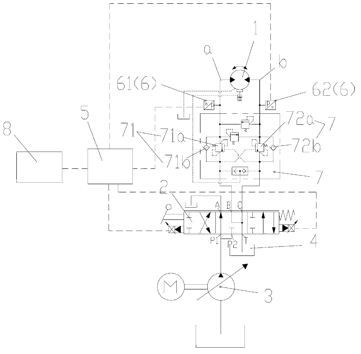
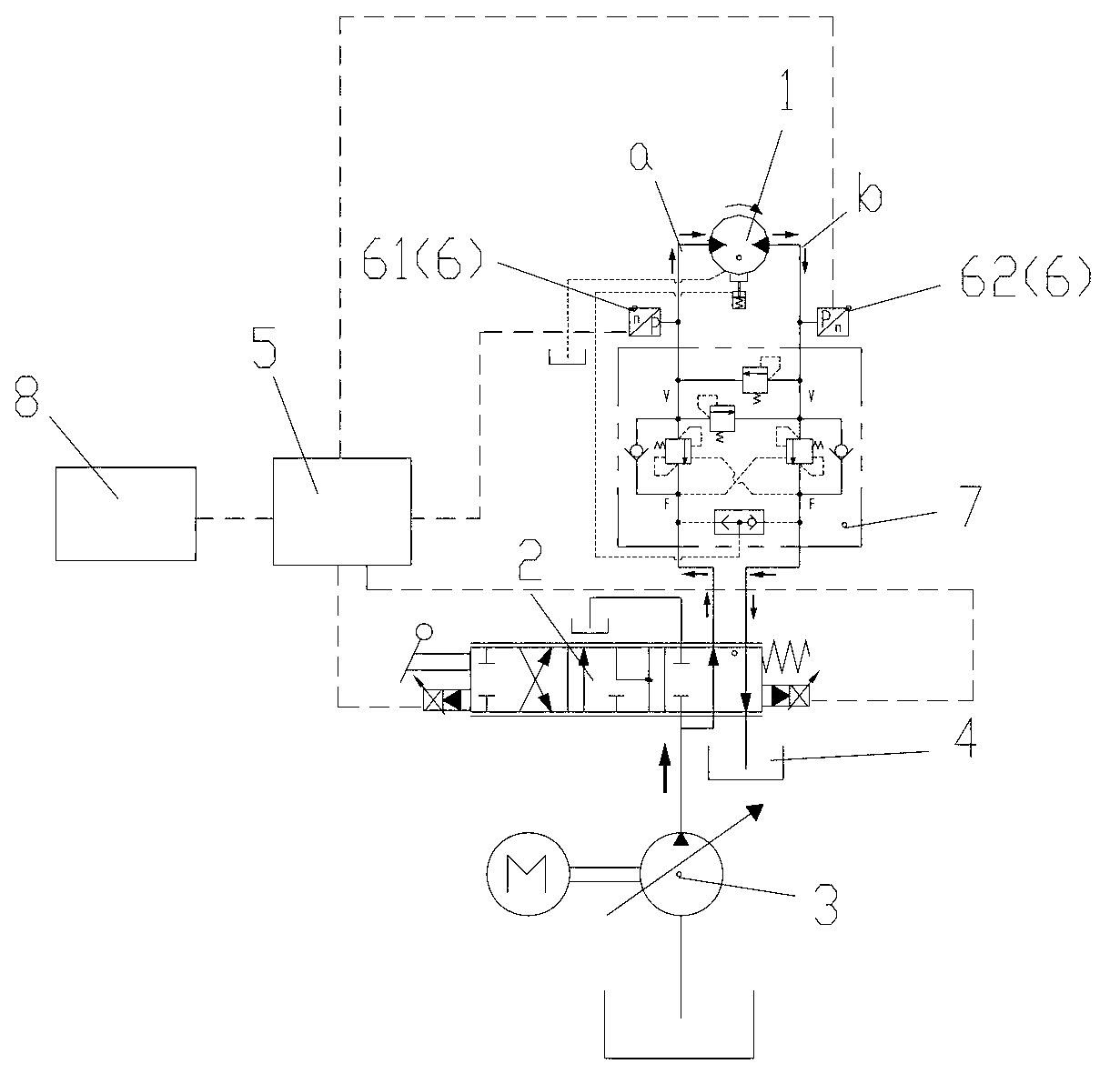
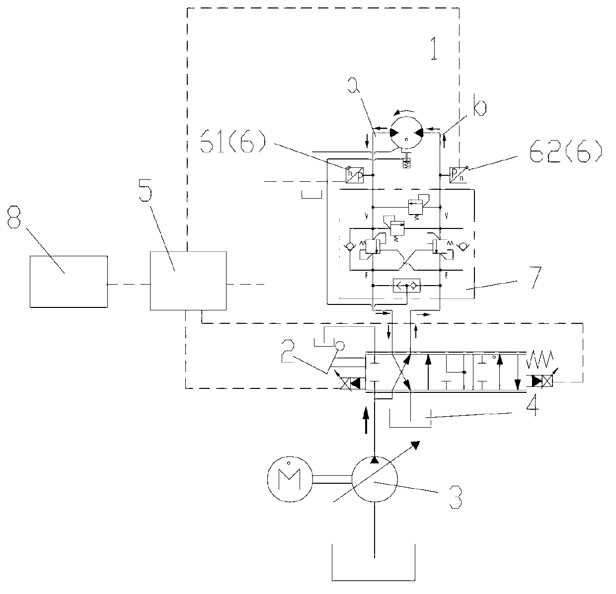
[0038]In the present invention, the concrete pump truck in the concrete pumping equipment provided by the present invention will be taken as an example to introduce the hydraulic system for controlling the rotation of the arm frame provided by the present invention. It should be noted that the concrete pump truck is only a part of the present invention A preferred embodiment, other fields that can be used for boom slewing control, such as cranes, can also be applied to the hydraulic system provided by the present invention, and the present invention does not limit the deformation of such application fields, which should also fall into the scope of the present invention within the scope of protection.

[0039] Specific embodiments of the present invention will be described in detail below in conjunction with the accompanying drawings. It should be understood that the specific embodiments described here are only used to illustrate and explain the present invention, and are not i...


PUM


Abstract

The invention discloses a hydraulic system for controlling rotation of a boom and a control method thereof. The hydraulic system comprises a hydraulic motor, a main valve, a hydraulic pump and an oil tank. When the main valve controls the hydraulic motor to rotate, an oil inlet passage of the hydraulic motor is communicated with the hydraulic pump, and an oil return passage is communicated with the oil tank. After the main valve controls the hydraulic motor to stop rotating, the oil inlet passage and the oil return passage are both locked. The hydraulic system comprises a controller and a detection device. After the main valve controls the hydraulic motor to stop rotating, the detection device is capable of detecting pressure value of the oil return passage, and the controller controls the degree of opening of the main valve based on the pressure value so as to enable the oil return passage to be communicated with the oil tank. Therefore, when the boom starts to stop rotating and the oil inlet passage and the oil return passage are locked, the degree of opening of the main valve is controlled based on the pressure changes of the oil return passage so that the oil return passage can be communicated with the oil tank again, pressure cannot be accumulated in the oil return passage, and thus rebounding occurring after the boom stops rotating is avoided. The invention further discloses concrete pumping equipment provided with the hydraulic system for controlling rotation of the boom.

Description

technical field [0001] The invention relates to the field of hydraulic control for arm frame rotation, in particular to a hydraulic system for controlling arm frame rotation, a control method and concrete pumping equipment using the hydraulic system. Background technique [0002] Among all kinds of construction machinery, boom slewing conditions are often used, such as concrete pump trucks in concrete pumping equipment, or tire-type cranes, etc. Among them, the concrete pump truck is a modern construction equipment used for continuous concrete pouring construction. It has the advantages of flexible maneuvering, high construction efficiency, good construction quality, and low environmental pollution, and is widely used in modern building construction. In the concrete pump truck, the distribution point can be conveniently changed through the swing or rotation of the boom, where the rotation of the boom is usually driven by a hydraulic motor. Due to the heavy weight of the bo...

Claims


Application Information

Patent Timeline
IPC IPC(8): F15B21/08F15B13/04
CPCF15B2211/8606F15B2211/50527F15B2211/6313F15B2211/853F15B20/007E02F9/2296F15B2211/20546F15B2211/7058F15B2211/665F15B2211/327
Inventor 秦晓峰刘如意
Owner ZOOMLION HEAVY IND CO LTD
Learn More