
Electrodeless lamp

An electrodeless lamp and lampshade technology, applied in the field of lighting, can solve the problems of increasing lamps, complex structure, large contact thermal resistance, etc., and achieve the effects of good heat dissipation, high color rendering, and prolonged life.

Inactive Publication Date: 2013-05-29
窦敏江
View PDF0 Cites 0 Cited by
  • Summary
  • Abstract
  • Description
  • Claims
  • Application Information

AI Technical Summary

Problems solved by technology

Such a structure has large contact thermal resistance, narrow space, small heat flux, and complex structure, which limits the application of high-frequency electrodeless lamps.
[0004] The existing electrodeless lamps have spherical, cylindrical and circular shapes, etc. In some specific occasions, such as squares, and places that need to be brightened, it is necessary to increase the number of lamps, resulting in material costs

Method used


Image

  • Electrodeless lamp

Examples


Embodiment Construction

[0014] The preferred embodiments of the present invention will be described in detail below in conjunction with the accompanying drawings, so that the advantages and features of the present invention can be more easily understood by those skilled in the art, so as to define the protection scope of the present invention more clearly.

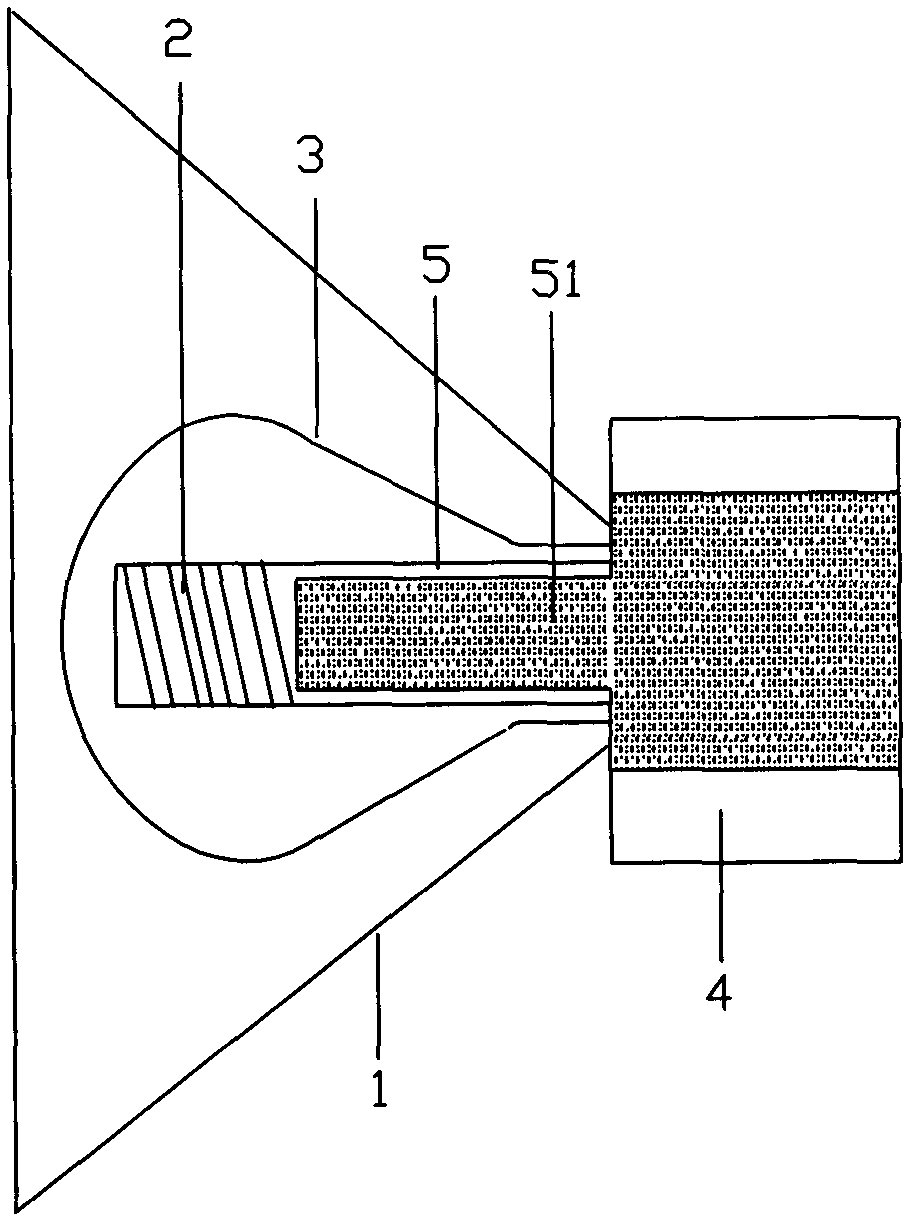
[0015] see figure 1 , an interesting electrodeless lamp, comprising: a light bulb 3, a power coupler 2, a lampshade 1 and a cooling device 4.

[0016] The power coupler 2 includes a liquid 51 and an inner cavity 5. The inner cavity 5 extends to the inside of the heat sink 4. The heat generated by the power coupler 2 is transferred to the heat sink 4 by the liquid 51 filled in the inner cavity 5 of the power coupler. The heat is released from the outside to ensure that the ambient temperature inside the bulb 3 is within a certain range.

[0017] The lampshade 1 gradually increases from the inside to the outside in the shape of a trumpet, and is p...


PUM


Abstract

The invention discloses an electrodeless lamp which comprises a lamp bulb, a power coupler, a lampshade and a radiating unit. The power coupler comprises liquid and an inner cavity. The lampshade increases from the inside to the outside in a horn shape, and placed externally on the outer surface of the lamp bulb. Due to the method, the electrodeless lamp is capable of being good in radiating performance, enabling the high-frequency electrodeless lamp coupler to work under a good temperature environment, improving the power and prolonging the service life of the lamp bulb, and meanwhile the eletrodeless lamp has highlight performance and high color rendering performance.

Description

technical field [0001] The invention relates to the field of lighting, in particular to an electrodeless lamp. Background technique [0002] The heat dissipation of the electrodeless lamp has always been a problem that needs to be solved. As the power increases, the heat dissipation problem becomes more and more serious. The large amount of heat generated by the power coupler cannot be dissipated in time, causing the core temperature to exceed the Curie temperature point and fail. [0003] The current technical solution is that the coupler magnetic core and the high-temperature wire generate a high-frequency magnetic field, and the excess heat energy generated by the coil is conducted to the outside of the aluminum base through the copper heat conducting rod or heat pipe in the middle. The base has two functions: one is to ensure the connection between the bulb and the coupler; the other is to transfer excess heat to the heat sink or lamp. Such a structure has large contact...

Claims


Application Information

Patent Timeline
Patent Type & Authority Applications(China)
IPC IPC(8): F21S2/00F21V29/00F21V3/02F21V29/503F21V29/71
Inventor 窦敏江
Owner 窦敏江
Learn More