Conveying device of covered stent

A technology of covered stents and delivery devices, which is applied in the field of medical devices, can solve the problems of complex operation, high processing precision requirements, complex structures of mandrel accessories and stent capture accessories, and achieve the effect of avoiding complex structures

Active Publication Date: 2013-06-05
BEIJING PERCUTEK THERAPEUTICS CO LTD
View PDF8 Cites 27 Cited by
  • Summary
  • Abstract
  • Description
  • Claims
  • Application Information

AI Technical Summary

Problems solved by technology

[0006] The technical problem to be solved by the present invention is that in the prior art, the cooperating mandrel fittings and stent catching fittings have complex

Method used


Image

  • Conveying device of covered stent
  • Conveying device of covered stent
  • Conveying device of covered stent

Examples


Embodiment 1

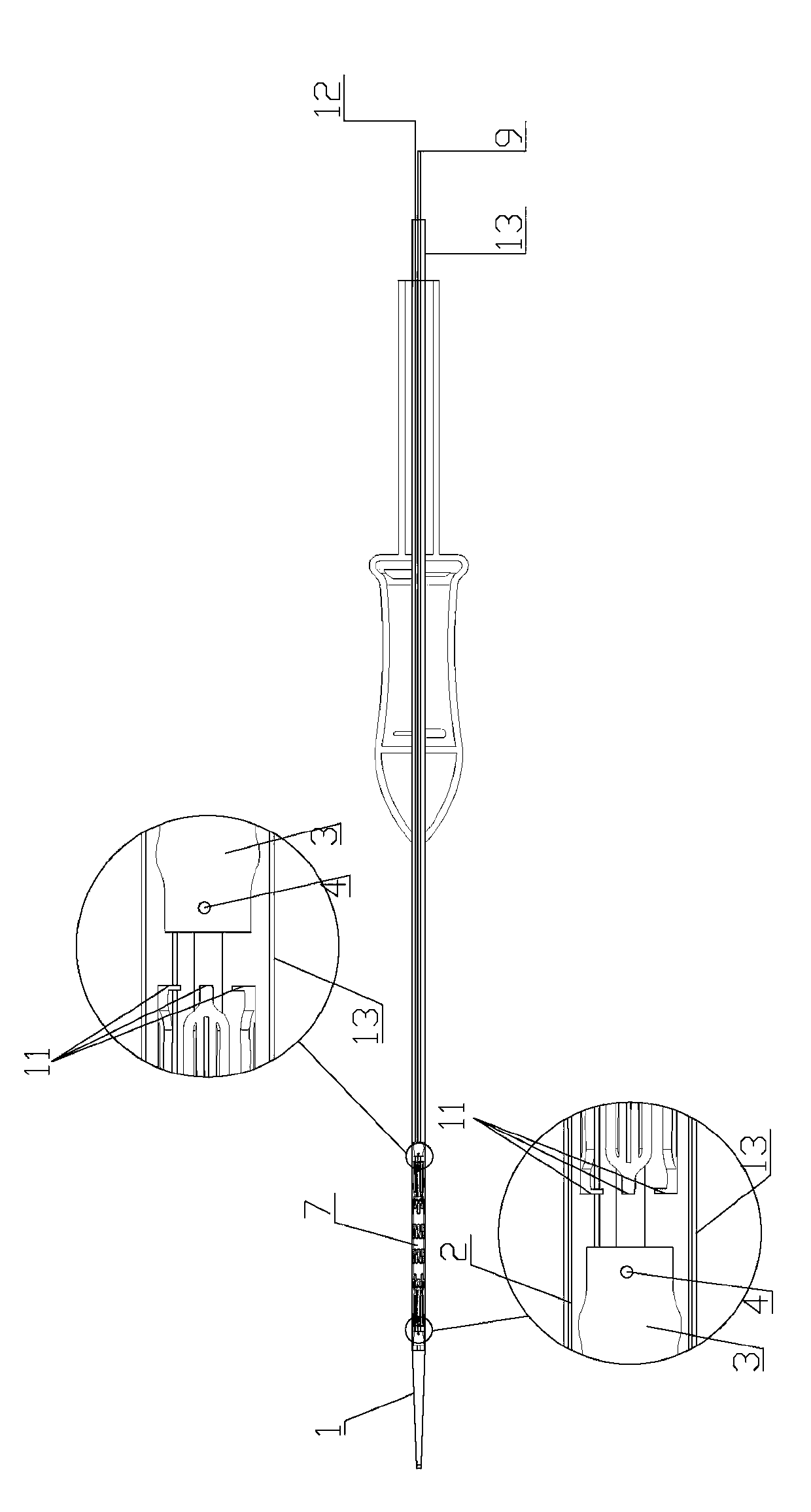
[0057] The delivery device of the stent graft described in this embodiment is as follows: figure 1 and 2 As shown, the guide head 1 is included, and the shape of the guide head 1 can be selected according to the needs. In this embodiment, the guide head 1 is conical; Cavity, the shape of the cavity can be selected according to the actual situation, in this embodiment the cavity is cylindrical;

[0058] Wire guide tube 9, one end of which is fixedly connected to the rear end of the guide head 1, and communicates with the cavity in the guide head 1, the connection between the guide wire tube 9 and the guide head 1 can be carried out as required Optionally, in this embodiment, the outer wall of the front end of the guide wire tube 9 is connected to the inner wall of the cavity at the large end of the guide head 1;

[0059] The sheath 2 is placed on the outer wall of the guide wire tube 9, and can move along the axial direction of the guide wire tube 9, and one end of the sheat...

Embodiment 2

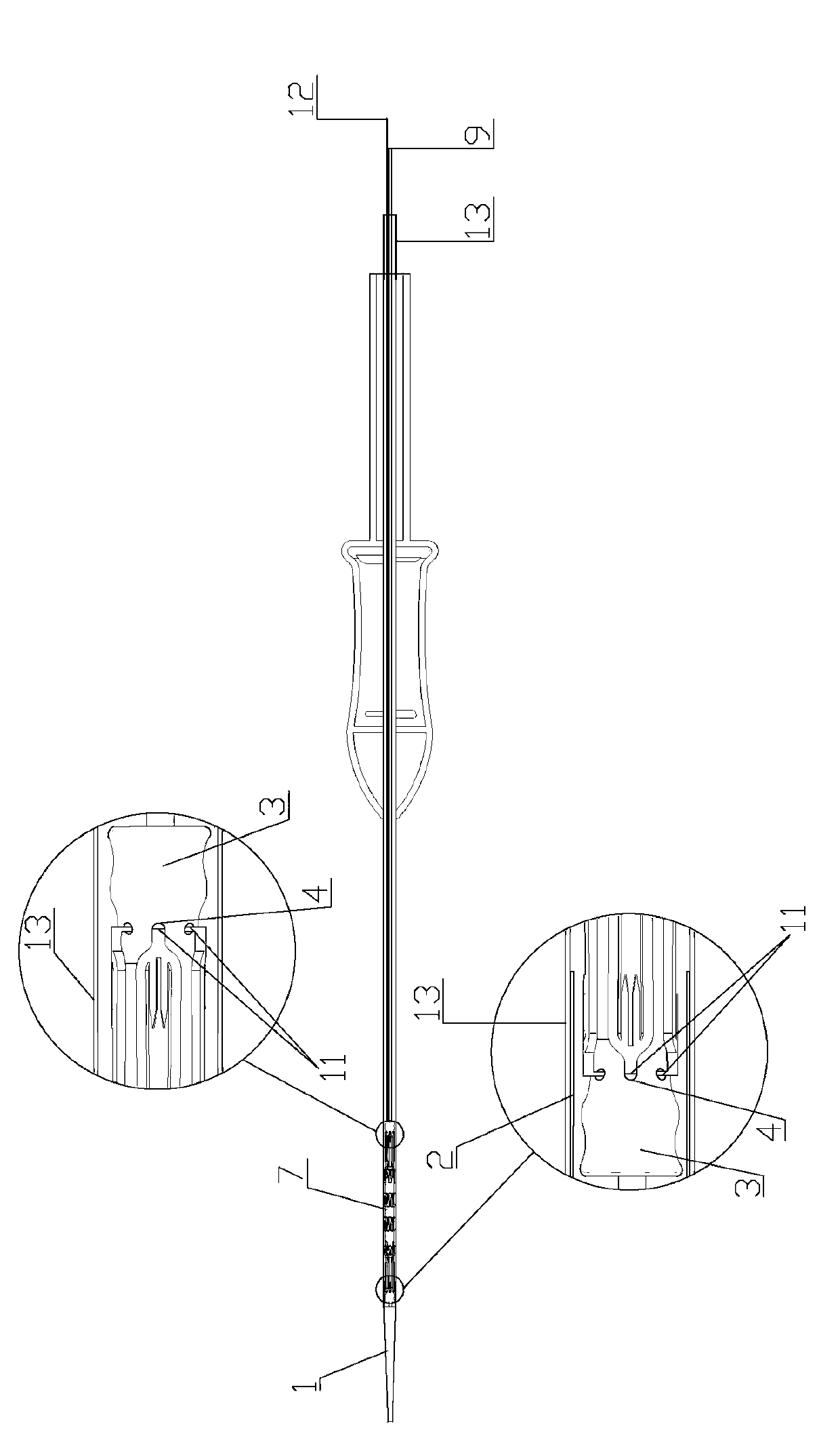
[0068] This embodiment is based on the foregoing embodiments, such as image 3 As shown, as an alternative implementation method, the proximal end of the selected stent-graft 7 is set as a bare stent, and the fixer 3 is one, which is arranged corresponding to the proximal end of the stent-graft 7 and close to the guide head 1, at the position of the big end, the fixer 3 is located in the sheath 2 as a whole, and the bare stent of the stent-graft 7 is located in the sheath 2 as a whole.

[0069] When the above-mentioned fixing device is assembled with the covered stent 7, the covered stent 7 can be assembled by moving the sheath 2 forward to expose the fixer 3. After assembly, move the sheath 2 backward to the outside of the bare stent to limit the The bending part 11 is located in the groove 4; when the stent graft 7 is released, the sheath 2 is moved forward until the part of the groove 4 on the holder 3 is exposed, and the bending part 11 on the bare stent will break away fr...

Embodiment 3

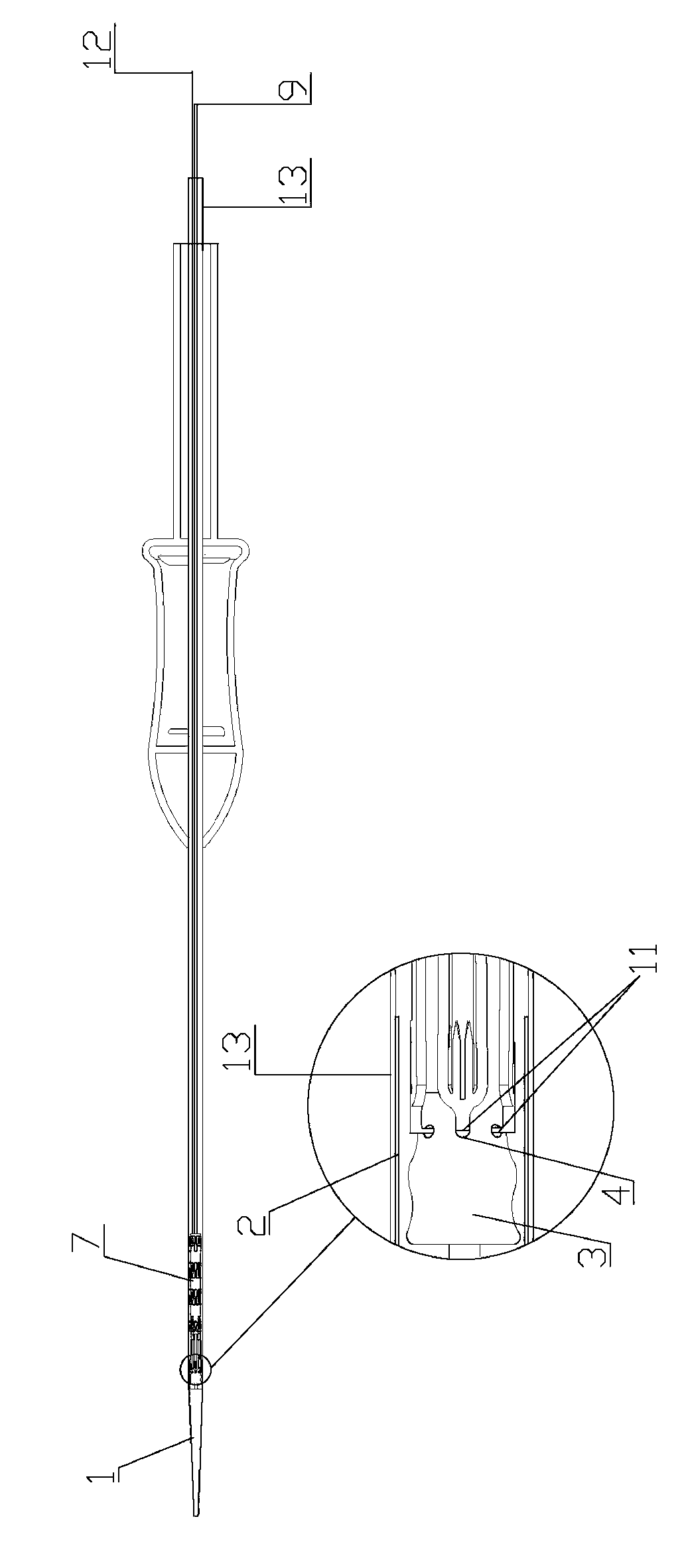
[0071] This embodiment is based on the foregoing embodiments, such as Figure 4 and 5 As shown, the groove 4 is provided with an opening 5, which is suitable for the stent graft 7 to be partially embedded in the groove 4 through the opening 5, so as to firmly limit the embedded part of the stent graft 7 in the groove 4, To prevent the embedded part from slipping out of the groove 4, the direction of the opening 5 can be selected according to actual needs. In this embodiment, the opening 5 of the groove 4 is set backward; the fixer 3 is provided with the Parts of the groove 4 and the opening 5 are all located in the sheath 2, and the rest of the fixer 3 is located in the sheath 2 or the outer tube 13. In this embodiment, the fixer 3 is located entirely in the In the sheath 2 and the outer tube 13; the stent body connected to the embedded part of the stent graft 7 is embedded in the opening 5. In this embodiment, the bent part of the bare stent with the stent graft 7 11 connec...


PUM


Abstract

The invention discloses a conveying device of a covered stent. The conveying device of the covered stent comprises a guiding head which is provided with a hollow cavity in the axial direction, a guiding wire pipe which is communicated with the hollow cavity, a protective sleeve, an external pipe and a fixing device, wherein one end of the guiding wire pipe is fixedly connected with the rear end of the guiding head; the protective sleeve is sleeved outside the external wall of the guiding wire pipe and is capable of moving along the axial direction of the guiding wire pipe; one end of the protective sleeve is connected with the rear end of the guiding head; the external pipe is sleeved outside the external wall of the guiding wire pipe and is capable of sliding along the axial direction of the guiding wire pipe; the external pipe is sleeved outside at least partial of the external wall of the protective sleeve; and the fixing device is sleeved outside the external wall of the guiding wire pipe and is capable of moving along the axial direction of the guiding wire pipe. The conveying device of the covered stent is characterized in that a groove is formed on the external wall of the fixing device; a portion of the groove, which corresponds to the covered stent, is inserted into the fixing device and the front end of the insertion portion and the rear end of the insertion portion abut against the wall of the groove; space for accommodating the inserted potion is formed between the protective sleeve and the guiding wire pipe; and a position on the fixing device, which is provided with the groove, is arranged in the protective sleeve. The conveying device of the covered stent is applicable to conveying the covered stent into a body and performing releasing during an operation.

Description

technical field [0001] The invention relates to a delivery device for a covered stent, which belongs to the field of medical instruments. Background technique [0002] The term "proximal end" in the present invention refers to the end close to the heart along the blood flow direction, "distal end" refers to the end away from the heart along the blood flow direction, and "end" refers to "near end" and "far end". At least one position, "both ends" refers to the two positions of "near end" and "distal end". [0003] Aortic aneurysm is a tumor body formed by local or diffuse abnormal expansion of the aortic wall that compresses surrounding organs and tissues. The tumor wall of this kind of tumor will gradually expand under the continuous impact of blood flow. When the tumor wall expands to a certain extent, it is very easy to rupture due to the impact of blood flow, causing massive aortic hemorrhage and posing a great threat to the life of the patient. . The surgical resectio...

Claims


Application Information

Patent Timeline
IPC IPC(8): A61B17/12A61F2/966
Inventor 肖家华杨凡徐靖钱兆琛
Owner BEIJING PERCUTEK THERAPEUTICS CO LTD
Why Eureka
Try Eureka