Jack

A technology of jacks and baffles, applied in the direction of lifting devices, etc., can solve the problems of inability to lift heavy objects, lateral displacement of jacks, and sinking of jacks, etc. The effect of a large contact area

Active Publication Date: 2013-06-05
NINGBO TIANYI SHAFT
View PDF5 Cites 2 Cited by
  • Summary
  • Abstract
  • Description
  • Claims
  • Application Information

AI Technical Summary

Problems solved by technology

When the car breaks down in the mud, or when it is necessary to lift heavy objects in the mud, the commonly used jack is placed directly in the mud, not only the weight of the jack will cause the jack to sink in the mud, but the bigger problem is When the jack is holding a heavy object, it cannot lift the heavy object, but the jack sinks deeper and deeper
At present, some jacks are equipped with a whole baffle near the conical head of the inner cylinder, but there is often more water in the muddy ground. Although the baffle can prevent the jack from sinking into the mud, it is difficult to pull it out after use, and it is difficult to pull it out in the muddy ground. It is easy to deflect the jack sideways

Method used


Image

  • Jack
  • Jack
  • Jack

Examples


Embodiment 2

[0023] Embodiment 2: Compared with Embodiment 1, the difference lies in that the way the jack is fixed in the muddy ground is different, and the rest are the same.

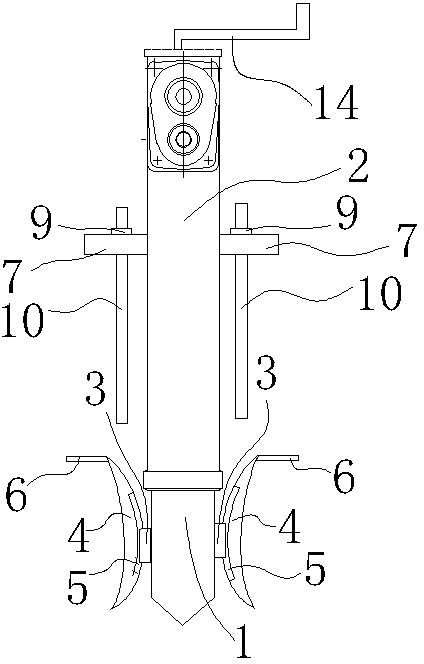
[0024] see Figure 3~6 , the plane end of the conical head is provided with a No. 2 baffle 101, and the No. 2 baffle 101 increases the contact area between the jack and the mud, so that the jack is not easy to sink when stressed. The No. 2 baffle plate 101 is provided with a No. 2 through hole 103, and the No. 2 through hole 103 is evenly distributed on the No. 2 baffle plate 101, and the air under the No. 2 baffle plate 101 is evenly circulated, which is convenient for jacking up Get off the silt side. The diameter of the No. 2 through hole 103 is preferably greater than one centimeter, so that the air circulation under the No. 2 baffle plate 101 is more thorough, and it is more convenient for the jack to pull out from the mud surface.

[0025] Perpendicular to the No. 2 baffle 101, there are at least four No. ...

Embodiment 3

[0026] Embodiment 3: Compared with Embodiment 1, the difference lies in that the way the jack is fixed in the muddy ground is different, and the rest are the same.

[0027] see image 3 , Figure 7 with Figure 8 , the two sides of the connection position between the conical head and the inner cylinder 1 are hinged with two movable No. 4 baffles 201. The No. 4 baffles 201 are used to support the jack in the muddy ground. The movable No. 4 baffles The board 201 can facilitate the jack to pick up in the muddy ground. The end of the No. 4 baffle 201 contacting the ground is arc-shaped. When the jack just touched the ground, the arc-shaped end kept a certain gap between the No. 4 baffle 201 and the ground to prevent one end of the No. 4 baffle 201 from being inserted into the silt, thereby hindering the four No. baffle plate 201 turns upwards.

[0028] The No. 4 baffle plate 201 is provided with a No. 3 through hole 205, and the No. 3 through hole 205 is convenient for the jac...


PUM


Abstract

The invention discloses a jack which comprises an inner barrel and an outer barrel. An end of the inner barre, close to the ground, is provided with a conical head. A second retaining plate is arranged at a plane end of the conical head and provided with second through holes, and at least four third retaining plates perpendicular to the second retaining plate are arranged. The second through holes are used for preventing the problem that the second retaining plate is not easy to pull up due to vacuum of a contact surface between the second retaining plate and sludge. The third retaining plates form side fixing parts so as to prevent side deflection of the jack. Ends of the third retaining plates, contacting with the sludge, are conical and easier to enter the sludge by reducing the contact area. The length of the third retaining plates is smaller than that of the conical head, the conical head is more suitable for quickly entering the sludge than the third retaining plates and firstly contacts the sludge so that the jack can be inserted into the sludge. The second through holes are uniformly distributed on the second retaining plate and can uniformize air flow below the second retaining plate so as to allow the jack to be pulled out of the sludge conveniently.

Description

technical field [0001] The invention belongs to a jack. Background technique [0002] Jack is a kind of light and small lifting equipment that uses a rigid top lifting part as a working device, and lifts a weight in a stroke by a top bracket or a bottom claw. According to the structural characteristics, it can be divided into three types: rack jack, screw jack and hydraulic jack. Jack is the simplest lifting equipment with a small lifting height (less than 1m). It has two kinds of mechanical and hydraulic. There are two types of mechanical jacks, the rack type and the screw type. Due to the small lifting capacity and laborious operation, they are generally only used for mechanical maintenance work, and are not suitable for bridge repairing. The hydraulic jack has compact structure, stable operation and self-locking effect, so it is widely used. Its disadvantage is that the lifting height is limited and the lifting speed is slow. The types of car jacks can be divided int...

Claims


Application Information

Patent Timeline
Patent Type & Authority Applications(China)
IPC IPC(8): B66F3/00
Inventor 叶培玉
Owner NINGBO TIANYI SHAFT
Why Eureka
Try Eureka