
Undersea suction anchor

A suction anchor and anchor ring technology, applied in anchor points, water conservancy projects, ship parts, etc., can solve the problem that the horizontal bearing capacity and overall stability cannot be effectively improved, the bearing capacity and overall stability are not much improved, and the seabed soil Erosion does not have much effect and other problems, to achieve the effect of preventing seabed erosion, increasing overall stability, and reducing the difficulty of recovery

Inactive Publication Date: 2013-06-05
OCEAN UNIV OF CHINA
View PDF5 Cites 41 Cited by
  • Summary
  • Abstract
  • Description
  • Claims
  • Application Information

AI Technical Summary

Problems solved by technology

Although this structure can improve the vertical bearing capacity of the anchor body, it cannot effectively improve the horizontal bearing capacity and overall stability, and has little effect on improving the erosion of seabed soil.
[0006] The self-installing suction anchor is characterized by controlled water injection into the airtight top compartment to achieve stable sinking, and by means of drainage and exhaust decompression in the compartment, a pressure difference between the top and bottom of the anchor is formed to achieve suction penetration. Its advantages are " Self-floating towing, stable sinking", but its reuse rate is low, and there is not much improvement in carrying capacity and overall stability.

Method used


Image

  • Undersea suction anchor
  • Undersea suction anchor
  • Undersea suction anchor

Examples


Embodiment Construction

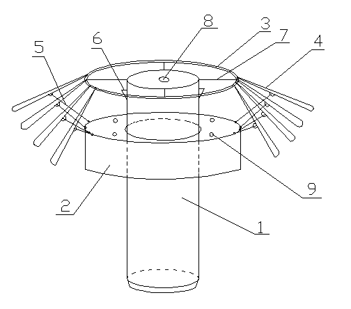
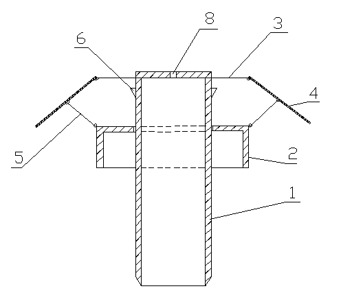
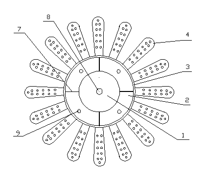
[0024] See attached Figure 1-Figure 3 , an embodiment of a submarine umbrella suction anchor of the present invention, comprising a main cylinder 1 with a closed top surface and an open lower end, and a main cylinder drainage hole 8 is arranged on the top surface of the main cylinder 1 . A tube skirt 2 is looped outside the main tube 2, and the tube skirt 2 includes a horizontal top surface and a cylindrical side wall, and a tube skirt drainage hole 9 is arranged on the horizontal top surface of the tube skirt. Two telescopic hooks 6 are symmetrically arranged on the cylindrical side wall on the upper part of the main cylinder 1 to position the skirt on the upper part of the main cylinder. An anchor ring 3 concentric with the main cylinder 1 is arranged at the upper end of the main cylinder 1, and anchor branches 4 are evenly arranged on the anchor ring 3, one end of the anchor branch 4 is hinged with the anchor ring 3, and the other end is connected to the skirt through the ...


PUM


Abstract

The invention discloses an undersea suction anchor which comprises a main drum, a top face of the main barrel is sealed, a lower end of the main barrel is opened, and a main barrel drainage hole is arranged on the top face of the main drum. The undersea suction anchor is characterized in that a barrel skirt is movably sleeved on the main drum, the barrel skirt comprises a horizontal top face and a barrel-shaped lateral wall, a barrel skirt drainage hole is formed in the horizontal top face of the barrel skirt, a telescopic hook locating the barrel skirt at the upper portion of the main barrel is arranged on the barrel-shaped lateral wall at the upper portion of the main barrel, an anchor ring concentric with the main barrel is arranged at the upper end of the main barrel, anchor branches are evenly arranged on the anchor ring, one ends of the anchor branches are hinged to the anchor ring, and the other ends of the anchor branches are hinged to the barrel skirt through inclined support rods. The whole vertical section of the suction anchor is in an umbrella shape, in the sinking process of the anchor body, along with landing-on-seabed of the barrel skirt, the anchor branches are driven by the inclined support rods to be gradually opened, and after the main barrel sinking is finished, the anchor branches cling to the surface of the seabed in a horizontal extending mode. The undersea suction anchor can improve the integral stability of the suction anchor, increases pulling resistance and horizontal bearing force, and reinforces wave-corrosion-resistance performance.

Description

technical field [0001] The invention belongs to the technical field of offshore wind power engineering and marine engineering, and relates to an offshore wind turbine foundation, an offshore platform mooring, a floating barrel positioning, a lighthouse, and a jacket structure foundation, in particular to a seabed suction anchor. Background technique [0002] With the accelerated development of offshore oil and gas resources exploitation and the rise of offshore wind power generation, the basic design of offshore drilling platforms and offshore wind farms has become an important topic in this field. Suction anchors, as a new type of offshore structural facility, have been widely used in ship mooring, buoy positioning, storage facilities, lighthouses, jackets, and offshore platforms. The suction anchor foundation is similar to a rigid short pile. The most widely used suction anchor in actual engineering is a barrel-shaped structure with a closed top and an open bottom. The si...

Claims


Application Information

Patent Timeline
IPC IPC(8): E02D5/80B63B21/27
CPCE02B17/0017E02B2017/0078
Inventor 刘红军李洪江王虎
Owner OCEAN UNIV OF CHINA
Learn More