Novel airproof oil pumping technology

A gas-proof and oil-pumping technology, which is applied to pumps with flexible working elements, liquid displacement machinery, machines/engines, etc., can solve the problems of reducing the fullness of the pump chamber, accelerating damage, shortening the pump inspection cycle, etc., to achieve The effect of reducing the influence of gas, increasing the service life, and reducing the difficulty of processing

Inactive Publication Date: 2013-06-05
欧阳才伟
View PDF0 Cites 0 Cited by
  • Summary
  • Abstract
  • Description
  • Claims
  • Application Information

AI Technical Summary

Problems solved by technology

There are two technically controversial issues about oil well pumps: one is whether the whole cylinder type oil well pump is better or the bushing type oil well pump is better; the other is whether it is better to have sand control grooves on the plunger or no sand control grooves
These gases occupy part of the volume of the pump chamber, which will reduce the fullness of the pump chamber, resulting in the lagging of the valve ball of the oil well pump, and even the phenomenon of "air lock"
"Hydraulic shock" also occurs during "air lock", causing vibration of the rod pumping system and accelerating its damage
As a result, pumping wells are frequently operated, shortening the pump inspection cycle, and increasing development costs

Method used


Image

  • Novel airproof oil pumping technology

Examples


Embodiment

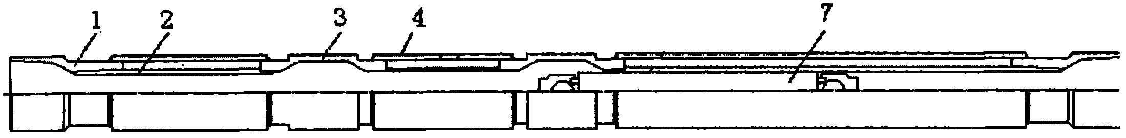
[0029] The novel air-proof oil pumping technique that the present invention relates to comprises the following steps:

[0030] (a) The plunger is at the bottom dead center, and both the fixed ball valve and the floating ball valve are closed;

[0031] (b) The plunger continues to move upward, the lower part of the plunger leaves the ventilation chamber, and the upper part of the plunger has entered the sealing chamber;

[0032] (c) The plunger reaches the top dead center of the pump;

[0033] (d) The plunger starts to stroke downwards, at this time the plunger swimming valve is closed, and when the plunger passes through the ventilation chamber, the gas in the ventilation chamber enters the oil pipe;

[0034] (e) The plunger continues to descend, the swimming valve is opened, and when the plunger passes through the ventilation chamber, the gas accumulated in the ventilation chamber enters the oil pipe.

[0035] The plunger goes back and forth once to realize an oil pumping c...


PUM


Abstract

The invention discloses a novel airproof oil pumping technology which comprises the following steps: (a) a plunger piston is located in the bottom dead center, a fixing ball valve and a floating ball valve are both closed; (b) the plunger piston continues to go up, the lower portion of the plunger piston leaves an air exchange cavity, and the upper portion of the plunger piston enters into a sealed cavity; (c) the plunger piston reaches the top dead center of a pump; (d) the plunger piston begins to stroke downward, the floating ball valve of the plunger piston is closed at present, and air in the air exchange cavity enters an oil pipe after the plunger piston passes through the air exchange cavity; and (e) the plunger piston continues to go down, the floating ball valve is opened, and the air gathered in the air exchange cavity enters the oil pipe when the plunger piston passes through the air exchange cavity. The novel airproof oil pumping technology achieves discharging of some gas in the process of stroke, influence of the gas is greatly reduced, and the amount of discharging liquid is increased. Due to the fact that reinforcement outer tubes are arranged between the air exchange cavities, when the oil well pump works normally, influence of axial alternating load on dangerous sections of pump barrels of the oil well pump is enabled to be greatly reduced, service life of the oil well pump is prolonged, and processing difficulty is lowered. The novel airproof oil well pump has the advantages of being low in cost, long in service life, convenient to use and maintain and suitable for popularization and quantity production.

Description

technical field [0001] The invention relates to a novel anti-air pumping process. Background technique [0002] Before the 20th century, the development of oil well pump technology at home and abroad was slow, and it was not until the middle of the 20th century that the whole barrel oil well pump was studied and produced simultaneously with the bushing type oil well pump. There are two technically controversial issues about oil well pumps: one is whether the whole barrel type oil well pump is better or the bushing type oil well pump is better; the other is whether it is better to have sand control grooves on the plunger or not to have sand control grooves. Until the 1980s, due to the significant improvement of the pump efficiency of the whole barrel pump, it is generally about 10% higher than that of the bushing pump, which prolongs the service life of the plunger pump barrel pair, and can save about 40% of high-quality steel. Instead of the bushing type oil well pump, the ...

Claims


Application Information

Patent Timeline
Patent Type & Authority Applications(China)
IPC IPC(8): F04B47/00
Inventor 欧阳才伟
Owner 欧阳才伟
Why Eureka
Try Eureka