Combination floating type brake pad

A brake pad, floating technology, applied in the direction of brake type, brake components, mechanical equipment, etc., can solve the problems of support failure, broken pawl damage, etc., to improve support performance and elasticity, ensure working life, and effectively The effect of increasing the braking area

Active Publication Date: 2013-06-05
BEIJING TIANYISHANGJIA NEW MATERIAL
View PDF7 Cites 6 Cited by
  • Summary
  • Abstract
  • Description
  • Claims
  • Application Information

AI Technical Summary

Problems solved by technology

However, in this technical solution, the fixed pawl supporting part and the spherical supporting surface are transitioned through a straight surface with a certain angle. Larger shear st

Method used


Image

  • Combination floating type brake pad
  • Combination floating type brake pad
  • Combination floating type brake pad

Examples


Example Embodiment

[0032] The following embodiments will be used to further illustrate the present invention with reference to the accompanying drawings.

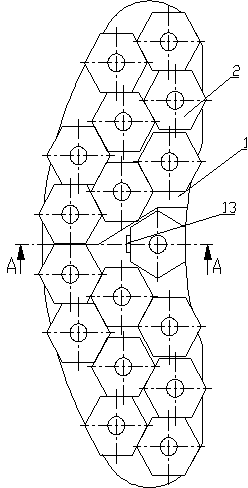
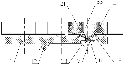
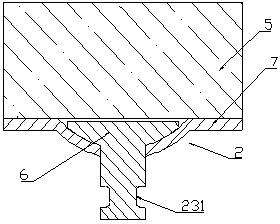
[0033] figure 1 , figure 2 It is a combined floating brake pad of the present invention, which includes a combined back plate formed by splicing and connecting two back plates 1; a plurality of friction blocks 2 arranged on the back plate 1; An elastic support piece 4 between the friction block 2 and the back plate 1, and a circlip 3 that connects the friction block 2 to the first back plate 1 in a floating manner.

[0034] Wherein, in order to make the friction blocks 2 arranged on the back plate 1 tightly arranged, the space of the back plate 1 is utilized as much as possible, and the combined back plate is composed of two asymmetrical back plates 1 The number of the positioning holes 11 on one of the back plates 1 is greater than the number of the positioning holes 11 on the other back plate 1. In this embodiment, the number of the positioning...


PUM


Abstract

The invention discloses a combination floating type brake pad. The combination floating type brake pad comprises a combination back plate formed by splicing two back plates together, a plurality of friction blocks arranged on the combination back plate, elastic support chips arranged between the friction blocks and the combination back plate and clamp springs connecting the friction blocks to a fist back plate in floatable mode. The elastic support chips comprise spherical support faces which are connected with spherical support portions of the friction blocks in fitting mode, guide holes which are formed at centers of bottoms of the spherical support faces and are suitable for locating portions of the friction blocks to penetrate through, and a plurality of support pawls arranged on outer sides of the spherical support faces, wherein the support pawls extend from edges of the spherical support faces to the bottoms of the spherical support faces and towards directions far away from the guide holes, connecting edges of the support pawls are connected with the edges of the spherical support faces through smooth transition sections, and extensions of support edges of the support pawls, which are opposite to the connecting edges of the support pawls exceed the bottoms of the spherical support faces. The brake pad solves the problem that due to the fact that pawls of elastic support pieces of an existing brake pad do not extend outwards but bend inwards, support of corresponding portions loses effectiveness.

Description

technical field [0001] The invention relates to a disc brake device applied to high-speed trains, in particular to a combined floating brake pad. Background technique [0002] With the trend of high-speed development of railway trains, higher requirements are placed on the braking performance of trains. In the train disc brake system, the brake pad is one of the key components, which directly rubs against the brake disc to absorb kinetic energy to make the train stop. Existing train brake pads are generally connected by rivets. When the train brakes at high speed, it is difficult to achieve a complete fit between the friction block and the brake disc. In this way, the brake pads are prone to cracking under the joint action of variable stress and high thermal load. Cracks, falling blocks, defects, etc. of the friction block will lead to cracks of the brake disc in serious cases, which will affect the braking effect of the high-speed train. [0003] In order to solve the abo...

Claims


Application Information

Patent Timeline
IPC IPC(8): F16D65/092F16D65/097F16D65/847
Inventor 吴佩芳
Owner BEIJING TIANYISHANGJIA NEW MATERIAL
Why Eureka
Try Eureka