Floating type brake pad used in rainy and snowy weather
A brake pad, floating technology, applied in the direction of brake parts, brake types, railway braking systems, etc., can solve problems such as large ice cubes, unsuitable use of brake pads, affecting the normal operation of brake pads, etc. , to achieve the effect of uniform distance, improved heat dissipation performance, and uniform heating
Active Publication Date: 2013-06-05
BEIJING TIANYISHANGJIA NEW MATERIAL
View PDF11 Cites 25 Cited by
- Summary
- Abstract
- Description
- Claims
- Application Information
AI Technical Summary
Problems solved by technology
However, the brake pad with the above structure is not suitable for use in rainy and snowy weather. This is because the friction debris accumulated in the heat dissipation holes of the friction block will solidify with the rain and snow to form larger ice cubes, which will affect the smoothness of the brake pad. normal work
Method used
View moreImage
Smart ImageViewing Examples

Examples
other Embodiment approach
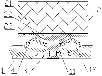
[0044] In other embodiments, what is used to realize the floating connection between the friction block 2 and the back plate 1 may also be a disc spring arranged between the friction block 2 and the back plate 1 .
Login to View More PUM
 Abstract
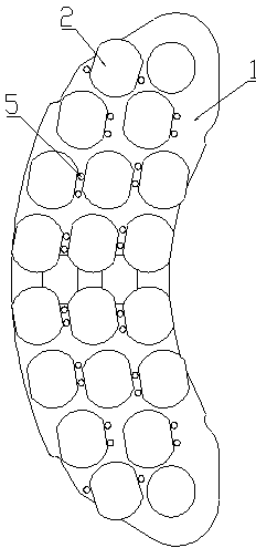
The invention discloses a floating type brake pad used in rainy and snowy weather, belonging to the technical field of train braking. The floating type brake pad used in the rainy and snowy weather comprises a back plate (1) and a plurality of friction blocks (2), wherein the back plate (1) is a sector ring structure with two ends transited through circular arcs; the friction blocks (2) are connected to the back plate (1) in a floatable manner; multiple layers of the friction blocks (2) are arranged from the inner ring to the outer ring of the back plate (1); an anti-rotation structure is arranged between the friction blocks (2) in adjacent layers; and the friction surface of each friction block (2) is a flat and smooth plane. The floating type brake pad used in the rainy and snowy weather solves the technical problems that the conventional brake pad is easy to accumulate friction scraps and is easy to condense with the rain and the snow to form a relatively big ice block to affect the normal work of the brake pad when being used in the rainy and snowy weather.
Description
technical field [0001] The invention belongs to the field of train braking, in particular to a floating brake pad for rainy and snowy weather. Background technique [0002] The disc brake structure for high-speed trains mainly includes brake discs and brake pads. Through the mutual friction between the brake disc and the brake pads, the kinetic energy of the moving vehicle or equipment is consumed to stop the train. The more common brake pads are fixedly connected by rivets between the back plate and the friction block. When braking this kind of brake pad, it is easy to appear that the friction block on the brake pad and the brake disc cannot be completely fitted. Phenomenon, so that the force can not evenly act on the friction block and the brake disc, resulting in cracks, missing blocks, and defects at the high stress point of the brake pad, resulting in a local high temperature area and shortening the brake pad. The service life affects the braking effect. [0003] For ...
Claims
Login to View More Application Information
Patent Timeline
 IPC IPC(8): F16D69/04
CPCF16D65/04F16D65/092F16D69/0408F16D2069/0433B61H5/00
Inventor 吴佩芳
Owner BEIJING TIANYISHANGJIA NEW MATERIAL
Features
- R&D
- Intellectual Property
- Life Sciences
- Materials
- Tech Scout
- Unparalleled Data Quality
- Higher Quality Content
- 60% Fewer Hallucinations
Learn More Browse by: Latest US Patents, China's latest patents, Technical Efficacy Thesaurus, Application Domain, Technology Topic, Popular Technical Reports.
© 2025 PatSnap. All rights reserved.Legal|Privacy policy|Modern Slavery Act Transparency Statement|Sitemap|About US| Contact US: help@patsnap.com