Power transmission apparatus

A technology of power transmission device and torque transmission, which is applied in the direction of transmission control, climate sustainability, road transportation, etc. It can solve the problems of fuel efficiency deterioration, pump load increase, undesired transmission belt, etc., and achieve the effect of preventing slippage

Active Publication Date: 2013-06-05
HONDA MOTOR CO LTD
View PDF6 Cites 7 Cited by
  • Summary
  • Abstract
  • Description
  • Claims
  • Application Information

AI Technical Summary

Problems solved by technology

[0008] The technique described in Patent Document 1 is structured as described above, thereby preventing breakage of the belt, but it is not desirable to make the belt slip from the viewpoint of durability.
In this regard, the torque limiting technique that prevents the slippage of the transmission belt by slipping the clutch is effective, but in order to be able to cope with any load, it is necessary to set a sufficiently large clutch engagement pressure, and the oil pressure energy increases, thereby increasing the pump load. deteriorating fuel efficiency

Method used


Image

  • Power transmission apparatus
  • Power transmission apparatus
  • Power transmission apparatus

Examples


Embodiment Construction

[0030] Next, modes for implementing the power transmission device of the present invention will be described with reference to the drawings.

[0031] 【Example】

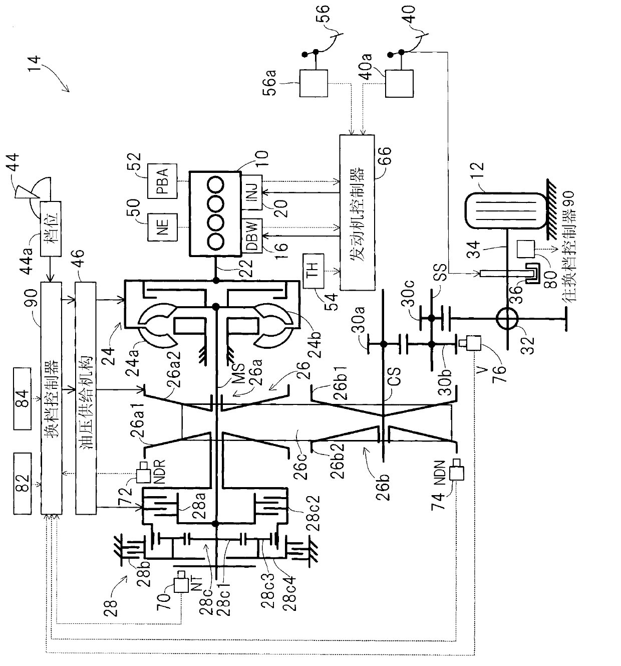
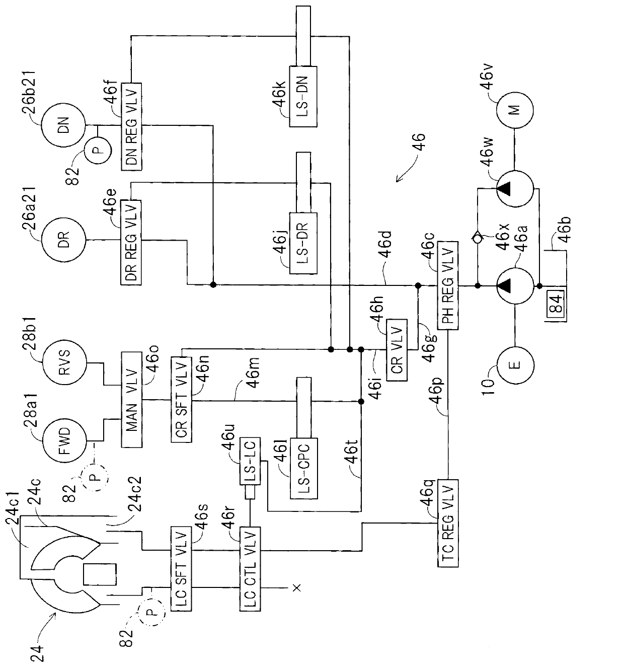
[0032] figure 1 is a schematic diagram showing a power transmission device of an embodiment of the present invention as a whole, figure 2 yes figure 1 The hydraulic circuit diagram of the hydraulic supply mechanism shown.

[0033] exist figure 1 In , reference numeral 10 denotes an engine (internal combustion engine (drive source)). Engine 10 is mounted in a vehicle 14 having drive wheels 12 (vehicle 14 is partially shown with drive wheels 12 etc.).

[0034] The mechanical connection between the throttle valve (not shown) arranged in the air intake system of the engine 10 and the accelerator pedal arranged on the bottom surface of the driver's seat of the vehicle is interrupted, and the DBW (Drive By Wire: drive by wire) mechanism 16 is connected, and is opened and closed through DBW mechanism 16.

[0035] The...


PUM


Abstract

The invention provides a power transmission apparatus which can prevent sliding of a drive pulley when a non-expected inertial force is inputted into a continuously variable transmission (CVT) from a pavement side in vehicles mounted with the continuously variable transmission. The power transmission apparatus comprises the CVT and a clutch (28a) in series arrangement with the CVT, wherein the CVT is composed of a driving / driven pulley connected with a driving source (an engine) mounted in the vehicle, and the drive pulley. The power transmission apparatus determines whether an output torque of the driving source is reduced. According to the output torque of the driving source and the input torque composed of the inertia torque, and pre-set friction coefficient of the drive pulley, the transmission torque of the drive pulley is calculated. Meanwhile, the transmission torque of the clutch is controlled during a driving state, so that the transmission torque of the clutch is more than the input torque and less than the transmission torque of the drive pulley (S202-S214).

Description

technical field [0001] The present invention relates to a power transmission device, and more particularly, to a power transmission device for a vehicle having a continuously variable transmission and a clutch. Background technique [0002] When the vehicle is suddenly decelerated by applying panic brake or the like while running, the rotation on the drive shaft is suddenly decelerated, and the inertial force acting from the drive wheel (road surface) side rapidly increases. When the transmission mounted on the vehicle is a continuously variable transmission, this inertial force acts on the continuously variable transmission as an excessive load. [0003] Therefore, the technology described in Patent Document 1 proposes to consciously cause the belt to slip (slip) by making the adjustment line pressure supplied to the hydraulic actuator of the continuously variable transmission lower than a reference value when a sudden deceleration state is detected. [0004] In addition, ...

Claims


Application Information

Patent Timeline
IPC IPC(8): F16H61/662
CPCF16H2061/6618F16H61/662Y02T10/76F16H61/66272
Inventor 栉山裕之小形卯京滑川健一
Owner HONDA MOTOR CO LTD
Why Eureka
Try Eureka