Multifunctional valve and multifunctional valve combination valve

A multi-functional valve and combined valve technology, applied in multi-way valves, valve details, valve devices, etc., can solve the problems of piston and cylinder end cover wear, piston and cylinder end cover damage, piston cylinder short service life, etc. , to avoid collision wear, increase resistance and prolong service life

Inactive Publication Date: 2013-06-05
皇甫美蓉
View PDF5 Cites 9 Cited by
  • Summary
  • Abstract
  • Description
  • Claims
  • Application Information

AI Technical Summary

Problems solved by technology

Not only can it produce a lot of collision noise, but it will inevitably cause serious wear to the piston and cylinder end cover
After being used for a period of time, it will inevit

Method used


Image

  • Multifunctional valve and multifunctional valve combination valve
  • Multifunctional valve and multifunctional valve combination valve
  • Multifunctional valve and multifunctional valve combination valve

Examples


Example Embodiment

[0024] Example 1

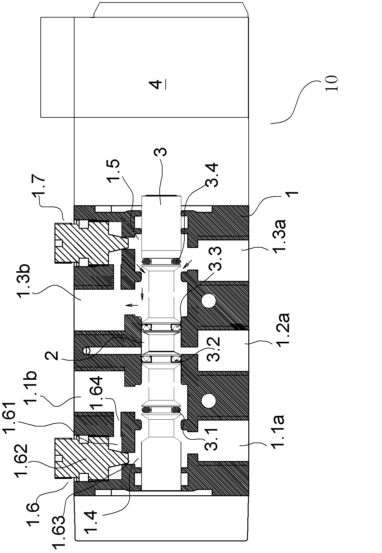
[0025] Such as figure 1 As shown, the multifunctional valve 10 includes a valve body 1 with a valve cavity 2 and a valve stem 3 installed in the valve cavity 2. The valve body 1 is provided with an intermediate inlet 1.2 for pressure medium to enter. a and left inlet 1.1a and right inlet 1.3a for the selective entry of pressure medium, the other side of valve body 1 is provided with left outlet 1.1b and right outlet 1.3b for pressure medium to discharge, said left inlet 1.1a and valve cavity The left sub-cavity 1.4 in 2 is connected, the right inlet 1.3a is connected with the right sub-cavity 1.5 in the valve cavity 2, the left sub-cavity 1.4 is connected through the throttle valve 1.6 and the left outlet 1.1b, the right sub-cavity 1.5 is connected through the throttle valve 1.7 Connect with the right exit 1.3b.

[0026] Throttle valve 1.6 is an adjustable flow valve with adjustable flow. Valve body 1 is provided with a tapered spool valve cavity 1.61. The botto...

Example Embodiment

[0029] Example 2

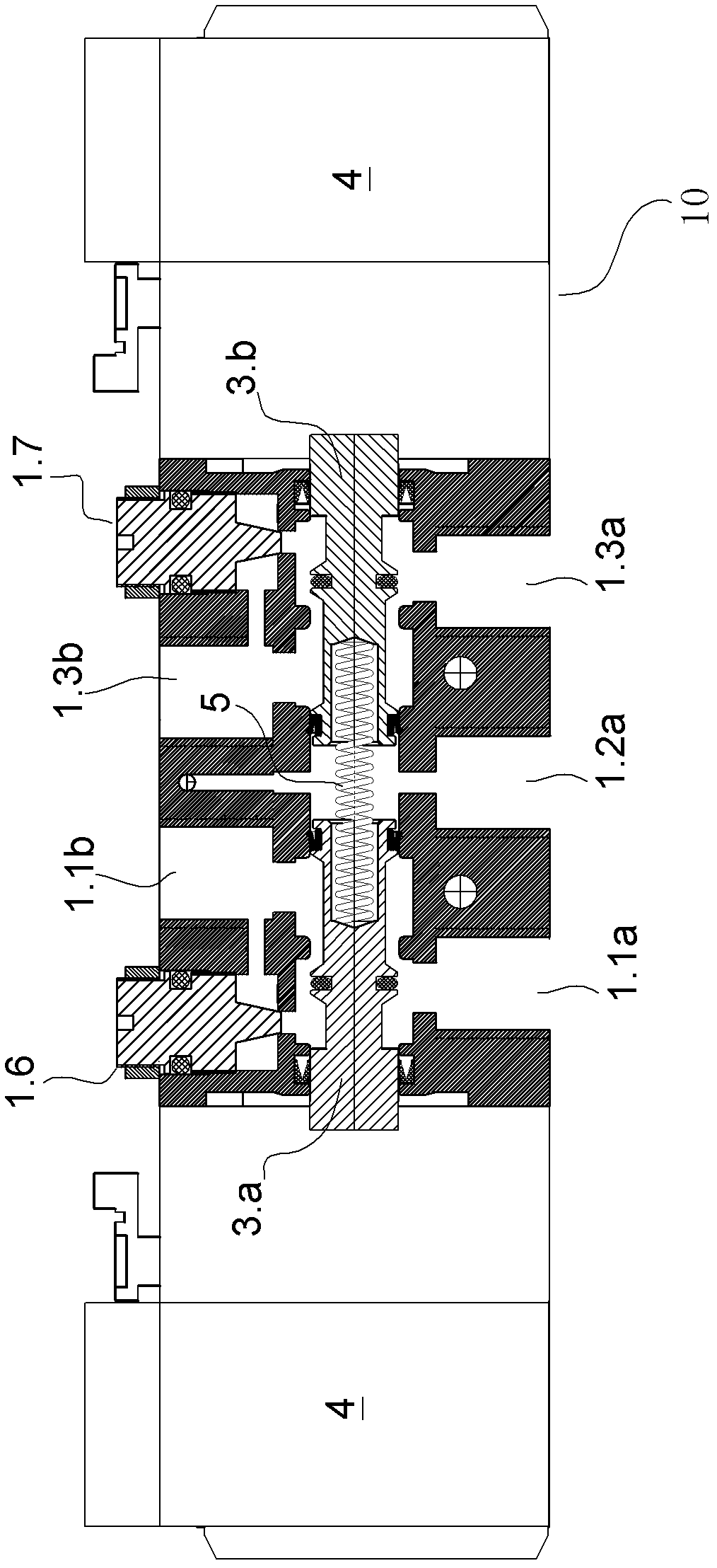
[0030] Such as figure 2 As shown, in this embodiment, the valve stem 3 is divided into a left valve stem 3.a and a right valve stem 3.b. The left and right valve stems are arranged between the left valve stem 3.a and the right valve stem 3.b. The moving elastic member 5 is similar to the embodiment.

Example Embodiment

[0031] Example 3

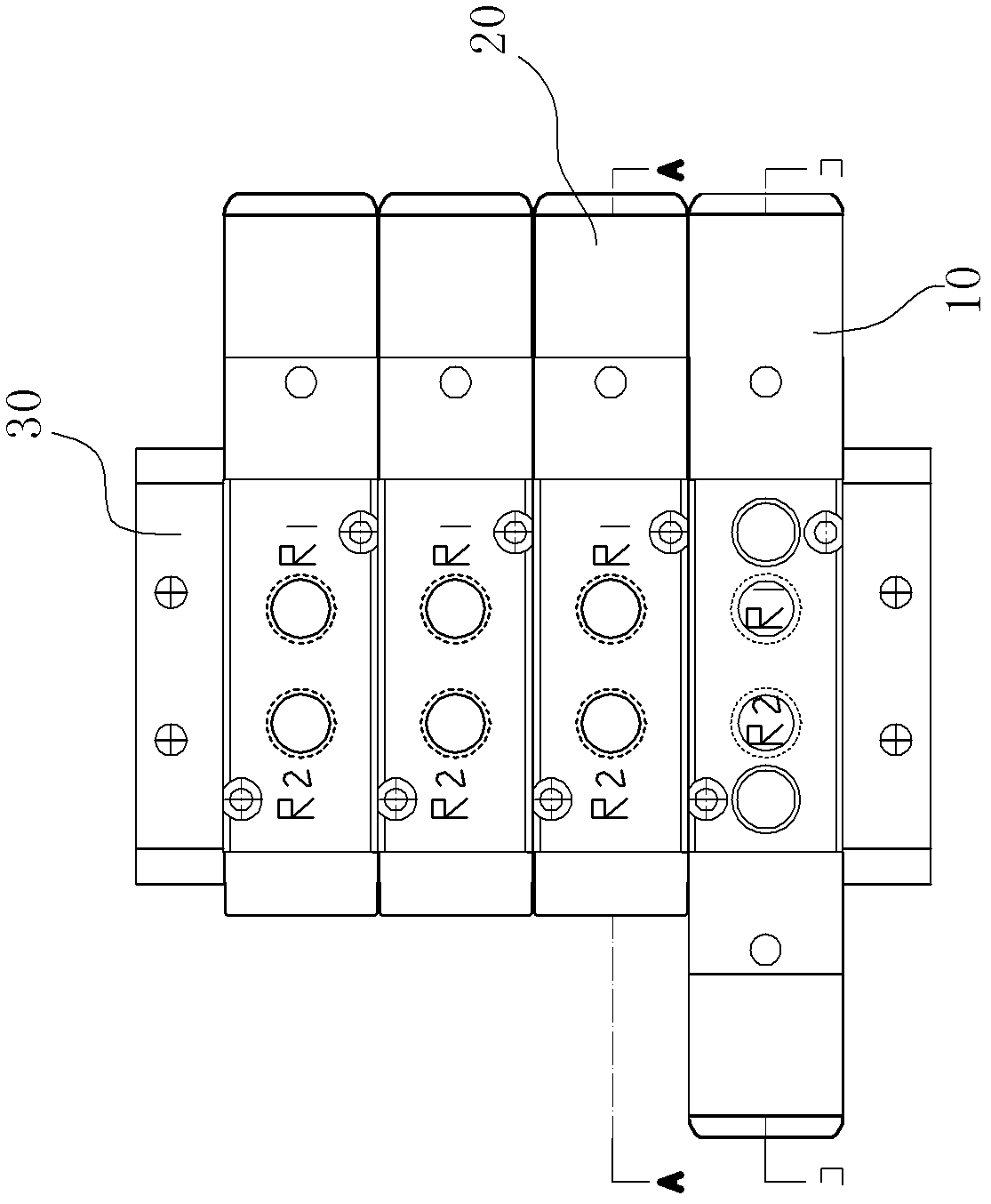
[0032] Such as image 3 As shown, a combination valve or valve island includes a multifunctional valve 10 in Embodiment 1 or 2, and the specific structure is described in Embodiment 1, and the description will not be repeated here;

[0033] Three control reversing valves 20;

[0034] And a manifold 30;

[0035] The left port 20.1b and right port 20.3b on one side of the steering valve 20 are respectively connected to the left cavity 40.1 and right cavity 40.2 of the piston cylinder 40, and the left return port 20.1a and the middle inlet on the other side of the steering valve 20 20.2a and the right return port 20.3a are respectively connected to the left flow channel 30.1, the middle flow channel 30.2 and the right flow channel 30.3 of the manifold 30;

[0036] The left inlet 1.1a, the middle inlet 1.2a and the right inlet 1.3a of the multifunctional valve 10 are respectively connected to the left flow channel 30.1, the middle flow channel 30.2 and the right flow cha...


PUM


Abstract

The invention relates to a multifunctional valve and a multifunctional valve combination valve. The multifunctional valve and the multifunctional valve combination valve comprise a valve body, a valve cavity which is arranged in the valve body and a valve rod which is arranged in the valve cavity, wherein a middle inlet, a left inlet and a right inlet are arranged on one side of the valve body, the middle inlet is used for the entering of pressure mediums, the left inlet and the right inlet are used for the selective entering of the pressure mediums, a left outlet and a right outlet are arranged on the other side of the valve body, the left outlet and the right outlet are used for the discharging of the pressure mediums, and the left inlet and the left outlet and the right inlet and the right outlet are selectively communicated in a corresponding mode through the matching of the valve cavity and the valve rod. The multifunctional valve and the multifunctional valve combination valve are characterized in that the left inlet is communicated with a left cavity correspondingly, the right inlet is communicated with a right cavity correspondingly, and correspondingly, the left cavity and the right cavity are communicated with the left outlet and the right outlet through a left throttle valve and a right throttle valve. According to the multifunctional valve and the multifunctional valve combination valve, a piston can be slowly contacted with the end portion of a piston cylinder, the collision and the abrasion to a piston rod when the piston is moved rapidly are avoided, the service life of the piston cylinder is prolonged effectively, and meanwhile the operation safety of the piston cylinder and the stability of the piston cylinder are ensured.

Description

technical field [0001] The invention relates to the technical field of buffer valves and related valve groups. Background technique [0002] When the piston cylinder works at high speed or high pressure, the movement speed of the piston rod and the piston is very fast. In this way, when the piston quickly moves to the two limit positions of the front end and the rear end of the cylinder body, the piston and the end cover of the cylinder body will inevitably be closed. Collision. Not only can it produce a lot of collision noise, but it will inevitably cause serious wear and tear on the piston and the end cover of the cylinder block. After using for a period of time, it will inevitably cause certain damage to the piston and the end cover of the cylinder body; the higher the pressure, the faster the speed, and the shorter the service life of the piston cylinder. Contents of the invention [0003] The primary technical problem to be solved by the present invention is to prov...

Claims


Application Information

Patent Timeline
IPC IPC(8): F16K11/10F16K27/04F15B15/22
Inventor 皇甫岳伟
Owner 皇甫美蓉
Why Eureka
Try Eureka