
Ground source heat pump rock-soil heat exchange and rainwater collection and utilization united technology

A ground-source heat pump and rainwater collection technology, which is applied in heat pumps, water supply devices, drinking water devices, etc., can solve problems such as the decline in heat transfer capacity, and achieve the effects of improving heat transfer performance and improving urban public safety

Active Publication Date: 2013-06-05
重庆海润节能研究院
View PDF5 Cites 4 Cited by
  • Summary
  • Abstract
  • Description
  • Claims
  • Application Information

AI Technical Summary

Problems solved by technology

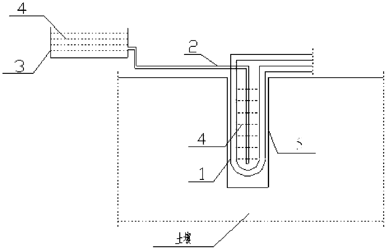
[0007] The ground source heat pump rock-soil heat exchange and rainwater collection and utilization joint technology of the present invention not only effectively solves the problem that the heat transfer capacity of the ground source heat pump system decreases during long-term operation in summer, but also improves the heat transfer performance of the ground source heat pump rock-soil heat exchanger At the same time, it can also use rainwater harvesting technology to replenish urban groundwater. While meeting the requirements for the use of renewable energy and energy conservation, it can also reduce rainwater, especially urban public safety hazards such as waterlogging caused by heavy rains, and improve the urban environment. public safety

Method used


Image

  • Ground source heat pump rock-soil heat exchange and rainwater collection and utilization united technology
  • Ground source heat pump rock-soil heat exchange and rainwater collection and utilization united technology

Examples


Embodiment Construction

[0032] Embodiments of the present invention are described in detail below, examples of which are shown in the drawings, wherein the same or similar reference numerals denote the same or similar elements or elements having the same or similar functions throughout. The embodiments described below by referring to the figures are exemplary only for explaining the present invention and should not be construed as limiting the present invention.

[0033] In describing the present invention, it should be understood that the terms "longitudinal", "transverse", "upper", "lower", "front", "rear", "left", "right", "vertical", The orientation or positional relationship indicated by "horizontal", "top", "bottom", "inner", "outer", etc. are based on the orientation or positional relationship shown in the drawings, and are only for the convenience of describing the present invention and simplifying the description, rather than Nothing indicating or implying that a referenced device or element...


PUM


Abstract

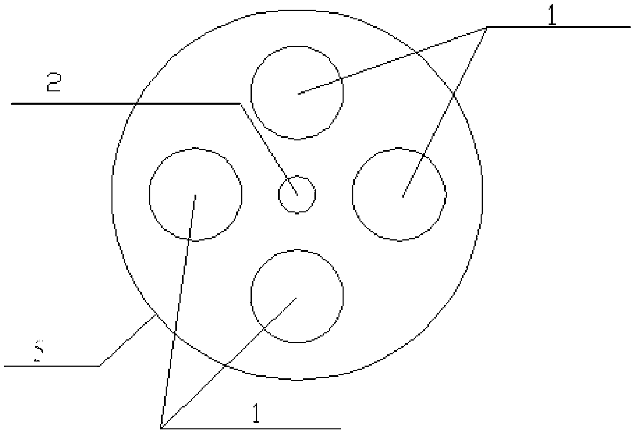
The invention provides a ground source heat pump rock-soil heat exchange and rainwater collection and utilization united technology. The ground source heat pump rock-soil heat exchange and rainwater collection and utilization united technology adopts at least one ground source heat pump buried tube heat exchange hole and at least one rainwater collecting device, a ground source heat pump rock-soil heat exchanger is arranged in the ground source heat pump buried tube heat exchange hole, and the rainwater collecting device is connected with the ground source heat pump buried tube heat exchange hole and used for leading water in the rainwater collecting device into soil surrounding the ground source heat pump buried tube heat exchange hole. The ground source heat pump rock-soil heat exchange and rainwater collection and utilization united technology can utilizes the ground source heat pump buried tube heat exchange hole to form powerful rainwater absorbing capacity, reduces urban rainfall flood pressure, improves rainwater storage and utilization level, decreases the dimension of an urban rainwater discharging system and saves investment. In addition, rock soil surrounding the heat exchange hole is infiltrated through stored rainwater, the comprehensive heat conductivity coefficient is improved, the problem that the buried tube heat exchange capability of a ground source heat pump system reduces in summer due to long-time operation is solved, and investment of the ground source heat pump system is saved. The double effects of rainwater collection and improvement of ground source heat pump heat exchange performance are achieved.

Description

technical field [0001] The invention belongs to the technical fields of new building energy utilization, urban drainage and rainwater collection and utilization. Background technique [0002] Ground source heat pump is a new renewable energy utilization method that utilizes shallow geothermal energy. It has significant advantages such as high efficiency and energy saving, low operating costs, long service life, strong reliability, good environmental protection benefits, and saving building space. [0003] During the operation of the ground source heat pump system, because the temperature of the soil around the rock-soil heat exchanger will continue to rise, the moisture in the soil will be driven to migrate outward, the soil around the rock-soil heat exchanger will continue to dry, and the heat transfer capacity of the buried pipe will continue to increase. decline. In order to make the ground source heat pump heat exchange system operate efficiently for a long time, mainta...

Claims


Application Information

Patent Timeline
IPC IPC(8): F25B30/06E03B3/02
CPCY02A20/108
Inventor 付祥钊杨勋居发礼童学江
Owner 重庆海润节能研究院
Learn More