Checking circuit for energy storage device terminal voltage

An energy storage circuit and device end technology, which is applied in the field of inspection circuits for the terminal voltage of energy storage devices, can solve the problems of long switching action time, complex production process, cumbersome calibration process, etc., and achieves fast channel switching speed, increased service life, Simple effect of peripheral circuit

Inactive Publication Date: 2013-06-05
TONGJI UNIV
View PDF6 Cites 6 Cited by
  • Summary
  • Abstract
  • Description
  • Claims
  • Application Information

AI Technical Summary

Problems solved by technology

The disadvantage of adopting this method is that the circuit has too high requirements for the accuracy of the A / D converter, which leads to an increase in the cost of the entire inspection circuit, and cannot be used in large-scale matching with energy storage devices. The node measurement channel is calibrated, the calibration process is cumbersome, and the production process is complicated. The single terminal voltage result obtained by this circuit is calculated by subtracting the two node voltages. The calculation process is complicated, and the accuracy of the final result cannot be reliably guaranteed.
[0004] The method of direct measurement using switching devices: If a relay is used as a switching device, whether it is a traditional mechanical relay or a currently popular solid-state relay, the switching time is relatively long, which affects the inspection time
The number of mechanical relay switches is limited, which affects the life of the entire inspection system, and the size of the relay is usually large, it is difficult to make the volume of the inspection system small
If the analog switch scheme is used, because the internal structure is mostly MOS circuits, the anti-interference ability is very poor, and it can be burned down by a slightly large overvoltage, and the test circuit cannot be used reliably for a long time
[0005] The current inspection methods generally require an independent power supply from an external power supply, but since the test locations of the energy storage units composed of each energy storage device in series are different, an isolated power module needs to be installed on each test unit, and with the entire energy storage The higher the voltage of the system, the higher the isolation voltage requirement of the power module, which brings a lot of inconvenience to the application of the energy storage system, and in some special occasions where the external power supply cannot be provided, these inspection methods cannot be used at all

Method used


Image

  • Checking circuit for energy storage device terminal voltage
  • Checking circuit for energy storage device terminal voltage
  • Checking circuit for energy storage device terminal voltage

Examples


Embodiment

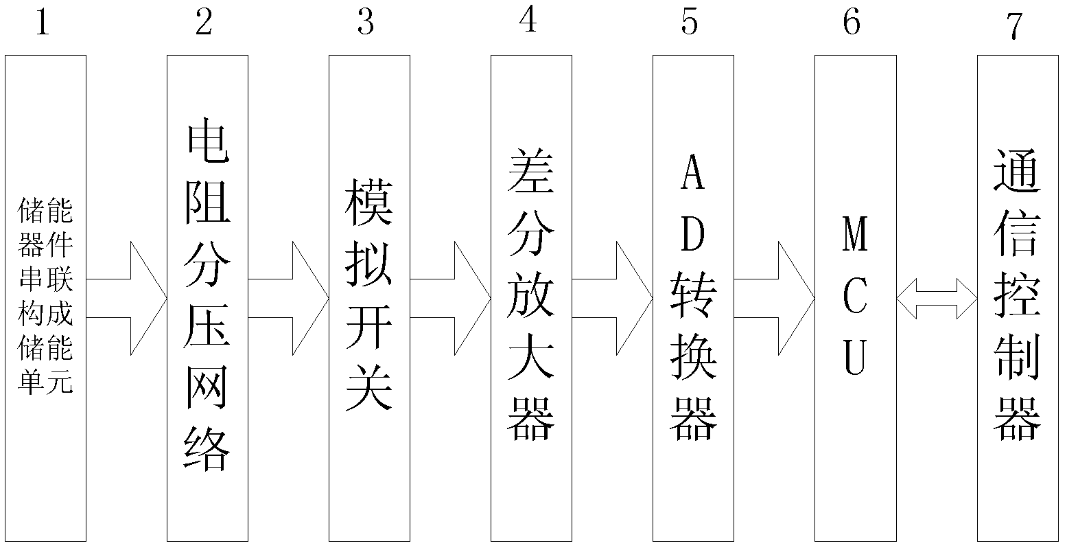
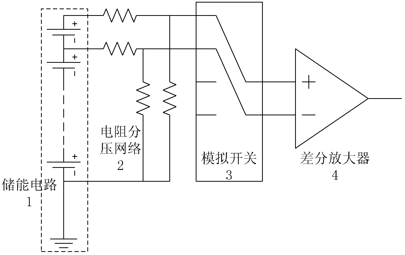
[0022] Such as figure 1 As shown, a patrol circuit for the terminal voltage of an energy storage device includes a resistor divider network 2 , an analog switch 3 , a differential amplifier 4 , an A / D converter 5 , and a microcontroller 6 . The resistance voltage divider network 2 is connected to the node of the energy storage circuit 1 composed of energy storage devices in series, and the voltage of the node is reduced proportionally to the acceptable voltage range of the analog switch 3 by means of resistance voltage division, and the analog switch 3 is connected to the resistance voltage divider network The output end of 2 and the input end of differential amplifier 4 are used for switching the node acquisition channel of energy storage circuit 1, and its specific structure is as follows figure 2 shown.

[0023] The differential amplifier 4 inputs the voltages of the two nodes through the analog switch 3, amplifies the voltage difference between the two nodes to the volta...


PUM


Abstract

The invention relates to a checking circuit for energy storage device terminal voltage. The checking circuit for the energy storage device terminal voltage comprises a partial pressure resistance network, an analogue switch, a differential amplifier, an analog to digital (A / D) converter and a microcontroller. The partial pressure resistance network is connected with nodes of an energy circuit which is composed of energy storage pieces connected in series and decreasing voltage of the nodes in equal proportion through a partial pressure resistance mode. The analogue switch is connected with an output terminal of the partial pressure resistance network and used for switching collection channels. The differential amplifier is connected with the analogue switch and amplifies voltage difference between the two nodes by inputting the voltage of the two nodes through the analogue switch. The A / D converter is connected with an output terminal of the differential amplifier, conducts AD sampling to output signals of the differential amplifier and conducts analog-to-digital conversion. The microcontroller is connected with an output terminal of the A / D converter and obtains terminal voltage of a corresponding node due to the fact that output signals the A / D converter multiplied by a coefficient. Compared with the prior art, the checking circuit for the energy storage device terminal voltage has the advantages of simple in circuit structure, quick in checking and the like.

Description

technical field [0001] The invention relates to a patrol circuit, in particular to a patrol circuit for the terminal voltage of an energy storage device. Background technique [0002] At present, the inspection methods for the monomer terminal voltage of energy storage devices can be roughly divided into two categories: the method of resistive voltage division and the method of direct measurement using switching devices. [0003] For the method of resistive voltage division, according to different test methods, it is mainly divided into common-mode measurement and differential-mode measurement. At present, most of the terminal voltage inspection circuits use the traditional common-mode measurement circuit, that is, divide the voltage of each node connected in series with the energy storage device to the acceptable voltage range of the A / D converter through a voltage-dividing resistor. By measuring the voltage of each node and subtracting it, the terminal voltage of each ene...

Claims


Application Information

Patent Timeline
Patent Type & Authority Applications(China)
IPC IPC(8): G01R19/25
Inventor 梁海泉谢维达钱存元吴雄文李玲李洋涛
Owner TONGJI UNIV
Why Eureka
Try Eureka