Microstrip patch type radio frequency identification (RFID) tag antenna

An RFID tag and microstrip patch technology, applied in the field of RFID tag antennas, can solve the problems of increased RFID tag antenna dimensions, inconsistent RFID tag antennas, poor reading distance, etc., to achieve high-bandwidth identifiable range, The effect of improved reading and writing distance

Inactive Publication Date: 2013-06-05
刘智佳
View PDF4 Cites 4 Cited by
  • Summary
  • Abstract
  • Description
  • Claims
  • Application Information

AI Technical Summary

Problems solved by technology

[0003] At present, the frequency bandwidths of RFID tag antennas used by various systems are still inconsistent in their high-frequency ranges. For example, Europe uses the 866-868MHz frequency band, while the United States uses the 902-928MHz frequency band. When switching between the existing RFID tag antennas, it is difficult to be identified in areas with different frequency bandwidths due to bandwid

Method used


Image

  • Microstrip patch type radio frequency identification (RFID) tag antenna
  • Microstrip patch type radio frequency identification (RFID) tag antenna
  • Microstrip patch type radio frequency identification (RFID) tag antenna

Examples


Example Embodiment

[0010] The specific implementation process of the present invention will be described in detail below in conjunction with the accompanying drawings.
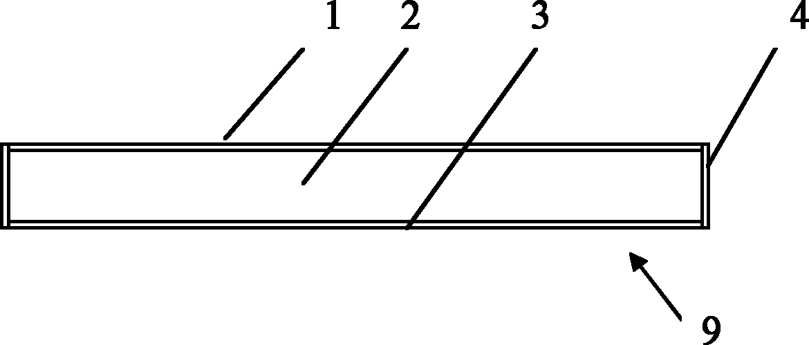
[0011] See figure 1 with figure 2 The microstrip patch RFID tag antenna 9 of the present invention has a substrate 2 and a radiating plate 1 attached to the upper surface of the substrate and a substrate bottom plate 3 respectively attached to the lower surface. The substrate 2 has short-circuit surfaces 4 on both sides.

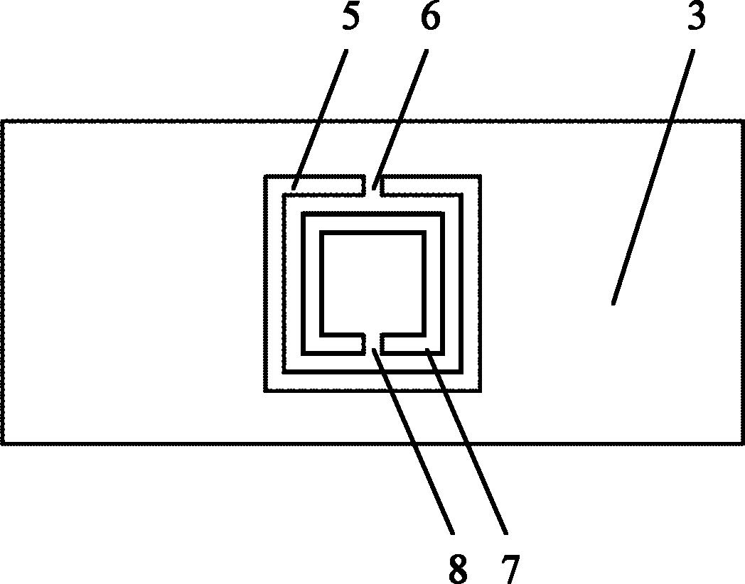
[0012] The substrate bottom plate 3 of the present invention has a first open annular groove 5 and a second open annular groove 7, and the first open annular groove 5 and the second open annular groove 7 are coupled to reduce the resonant frequency of the RFID tag antenna 9. Improve the reading distance of RFID tag antenna.

[0013] As a preferred embodiment of the present invention, both the first open annular groove 5 and the second open annular groove 7 are square, the first open annular groove 5 has a first open...


PUM


Abstract

The invention relates to a microstrip patch type RFID tag antenna. The RFID tag antenna (9) is provided with a radiant panel (1), a substrate (2) and a substrate base plate (3) and is characterized in that a first open circular groove (5) and a second open circular groove (7) are formed on the substrate base plate (3), by the aid of the coupling of the first open circular groove (5) and the second open circular groove (7), the resonant frequency of the RFID tag antenna (9) is reduced, and the reading distance of the RFID tag antenna (9) is increased. The RFID tag antenna (9) is miniaturized, low in loss and capable of achieving long-distance reading, simultaneously, the RFID tag antenna (9) is good in broadband matching performance, and the bandwidth frequency of the RFID tag antenna (9) is higher than that of the prior art.

Description

technical field [0001] The invention relates to an RFID tag antenna, in particular to a microstrip patch type RFID tag antenna. Background technique [0002] RFID (Radio Frequency Identification)——radio frequency identification technology, is a non-contact automatic identification technology realized by radio frequency communication. It consists of two main parts: electronic tag (tag) and reader (reader), with code The tag and reader perform contactless data transmission through the antenna to complete the automatic identification process at a certain distance. The current radio frequency identification system can be divided into low frequency system (30-300KHz), medium-high frequency system (3-30MHz) and ultra-high frequency and microwave system (300MHz-3GHz or greater than 33GHz) according to the frequency band used. As a high-tech and information standardization basis for fast, real-time and accurate collection and processing of information, it has been recognized by the...

Claims


Application Information

Patent Timeline
IPC IPC(8): H01Q1/38H01Q1/22
CPCH01Q1/12H01Q1/2225H01Q1/48H01Q9/0407
Inventor 刘智佳杜国宏
Owner 刘智佳
Why Eureka
Try Eureka