
Electronic component pin regulating device

A technology of electronic components and circuit boards, which is applied in the field of electronic component leg fixers, can solve problems such as installation defects, unfavorable production line time costs, and manual operation difficulties, so as to reduce the probability of product defects, facilitate manual operations, and avoid easily deformed effect

Inactive Publication Date: 2013-06-05
ASKEY TECH JIANGSU +1
View PDF4 Cites 1 Cited by
  • Summary
  • Abstract
  • Description
  • Claims
  • Application Information

AI Technical Summary

Problems solved by technology

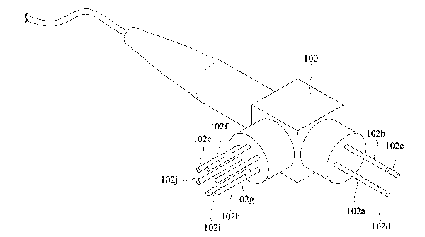
[0004]However, some electronic components may contain more than three pins, and when the pins are spatially staggered at positions on one side of the electronic component, It may cause difficulty in alignment with the connection points on the circuit board; as shown in Figure 1 As shown in , taking the Bi-directional optical sub-assembly (BOSA) in the optical transceiver module as an example, it has a transmitting end (Transmitter) composed of a laser diode (Laser Diode, LD) ) and a receiving end (Receiver) composed of a photodetector (PD), wherein the laser diode at the sending end has four pins 102a-102d, which are arranged in a quadrangular quadrilateral on the end face of the sending end end points; the light-sensing diode at the receiving end has six pins 102e-102j, which are arranged on the six end points of a hexagon on the end face of the receiving end; since these pins are not in common with the surface of the opposite circuit board The planar form is arranged on the end surface of the transmitting end or the receiving end, so the distance between each pin and the surface of the circuit board is not necessarily the same, so the pins need to be bent when installing and soldering, so that the pins are aligned and contacted At the connection point on the surface of the circuit board, at the same time, the metal pins are easily bent and deformed, which may cause manual operation troubles or cause installation defects during the process of leg assembly, installation and welding
[0005] Therefore, in the prior art, before the bidirectional transmission optical sub-module is installed and soldered on the circuit board, it is necessary to manually trim and cut the legs For the operation, place the pins one by one at the positions of the connection points on the circuit board, and start the welding action; in addition, due to the miniaturization of electronic components, the circuit layout of the circuit board is denser, which in turn causes the connection points to be more dense. The distance between them is very narrow, which leads to the difficulty and time-consuming of manual operation, and is not conducive to the time cost of mass production on the production line.

Method used


Image

  • Electronic component pin regulating device
  • Electronic component pin regulating device
  • Electronic component pin regulating device

Examples


Embodiment Construction

[0041] In order to fully understand the purpose, features and effects of the present invention, the present invention will be described in detail by the following specific embodiments in conjunction with the accompanying drawings, as follows:

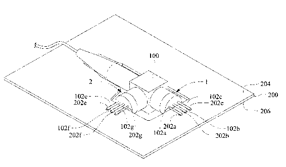
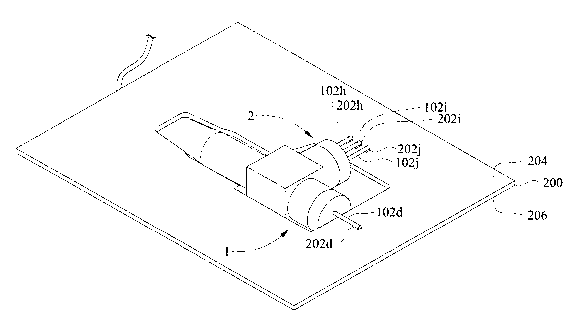
[0042] Please refer to Figure 2 to Figure 3 , figure 2 It is a schematic diagram of the electronic component foot adjuster of the present invention installed on the first surface of the electronic component and the circuit board; image 3 It is a schematic diagram showing that the electronic component leg fixer of the present invention is installed on the second surface of the electronic component and the circuit board. The electronic component leg adjuster 1 of the present invention is used for mounting the electronic component 100 on the circuit board 200, fixing and fixing the plurality of pins 102a-102j of the electronic component 100, so that the pins 102a-102j are connected There are a plurality of connection points 202a-202j ...


PUM


Abstract

The invention discloses an electronic component pin regulating device. When the electronic component pin regulating device is used for assembling an electronic component onto a circuit board, connecting pins of the electronic component are regulated and fixed so as to be connected with multiple connecting points on the circuit board in para-position mode. The electronic component pin regulating device comprises an insulating body and multiple channels, wherein the channels penetrate through the insulating body, each channel is provided with an inlet end and an outlet end respectively, the inlet ends correspond to the positions of the connecting pins on the electronic component, the outlet end correspond to the positions of the connecting points, and the connecting pins are regulated and fixed through the channels. Therefore, the electronic component pin regulating device can enable the connecting pins to be quickly and rightly connected with the multiple connecting points in para-position mode, further can enable the time required by procedures for installing the electronic component on the circuit board to be remarkably decreased, and facilitates manual operation.

Description

[0001] technical field [0002] The invention relates to an electronic component leg straightener, which is used for the leg straightening and fixing of the electronic component pins. Background technique [0003] Generally speaking, the pins of various commonly used electronic components are soldered to the connection points on the circuit board, so as to achieve the installation and electrical connection between the electronic components and the circuit board. These commonly used electronic components can be, for example, resistors, capacitors, transistors, transmission module components, receiving module components or transceiver module components, etc., which are soldered and electrically connected to the connection on the circuit board by protruding from the body of the electronic component. The position of the connection points on the circuit board is usually pre-arranged, and the distance between the connection points is very narrow. Therefore, before the electronic c...

Claims


Application Information

Patent Timeline
Patent Type & Authority Applications(China)
IPC IPC(8): H05K13/00B21F1/00
Inventor 彭国展谢青峰
Owner ASKEY TECH JIANGSU
Learn More