
Cathode for electrolysis cells

An electrolytic cell and cathode technology, applied in the field of cathodes for electrolytic cells, can solve the problems of irreconcilable requirements, high production costs, inability to use high-quality materials, etc., and achieve the effects of high-level cooling and large intervals

Inactive Publication Date: 2013-06-05
SGL CARBON SE
View PDF8 Cites 1 Cited by
  • Summary
  • Abstract
  • Description
  • Claims
  • Application Information

AI Technical Summary

Problems solved by technology

Furthermore, when individual components are involved, compromises must be made regarding optimal design, since in some cases the requirements between the individual components cannot be reconciled
Also, due to the frequent replacement of all materials such as cathode blocks, ramming mass, side fittings and insulation, high quality materials cannot be used lest the production cost of aluminum becomes prohibitive

Method used


Image

  • Cathode for electrolysis cells
  • Cathode for electrolysis cells
  • Cathode for electrolysis cells

Examples


Embodiment Construction

[0037] refer to Figure 2a and 2b , in each case from different perspectives, shows an electrolytic cell with an embodiment of the cathode 1 according to the invention. The cathode 1 shown is suitable for the extraction of aluminum from aluminum oxide using the Hall-Héroult process. In this case, the electrolytic cell is provided with two side walls 1a1 which, together with the bottom wall 1a2, serve to accommodate the electrolyte tank. In the case shown, the side walls 1 a 1 extend along the longitudinal sides of the cathode 1 . The side wall 1a1 is made of individual side wall pieces 1a3. The bottom wall 1a2 represents the upper or first part 1a of the cathode 1 . In this embodiment, the cathode 1 is produced from individual cathode blocks 11 .

[0038] In the exemplary embodiment shown, the lower part 1b of the cathode 1 comprises a plurality of connecting bodies 1b1 formed by trapezoidal bodies 1b2 in the lower part which taper downwards in a V-shape. The connecting ...


PUM


Abstract

The invention relates to a cathode (1) for an electrolysis cell for extracting aluminium from its oxide in an electrolysis bath, said cathode comprising an upper part (1a) facing the electrolysis bath, and a lower part (1b) provided with connections (1b1) for the supply line. According to the invention, the upper part (1a) and the lower part (1b) can be detachably connected, at least in sections, by means of an intermediate layer.

Description

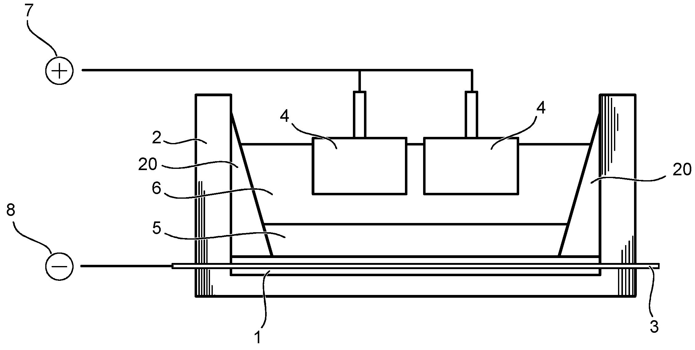
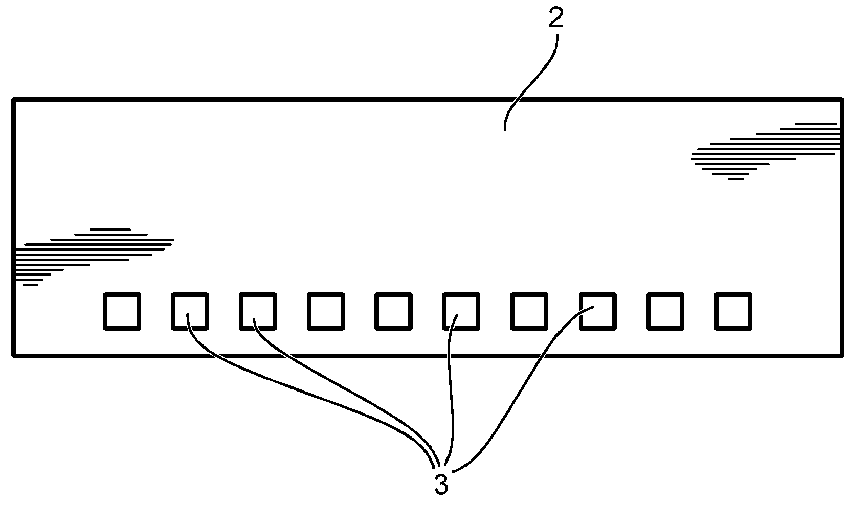
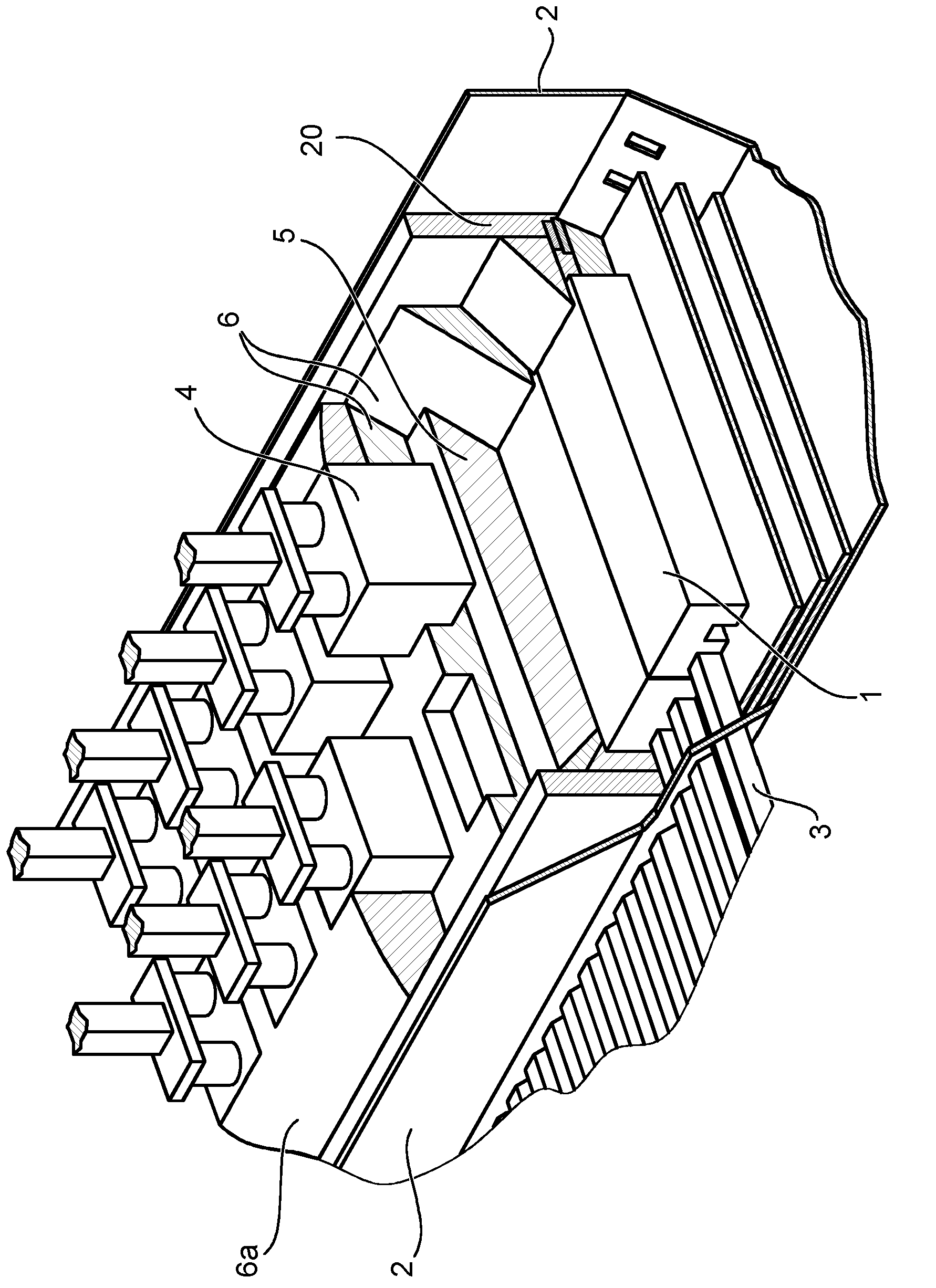
technical field [0001] The present invention relates to cathodes for electrolytic cells for the extraction of aluminum by molten salt electrolysis. Background technique [0002] At present, the Hall-Héroult (Hall-Erout) method is used in industry to extract aluminum from aluminum oxides. The Hall-Héroult method is an electrolytic process in which oxides of aluminum (Al 2 o 3 ) dissolved in molten cryolite (Na 3 [AlF 6 ]), the resulting mixture functions as a liquid electrolyte in an electrolytic cell. In principle, in Figures 1a to 1c The design of such an electrolytic cell for implementing the Hall-Héroult method is schematically depicted in , where Figure 1a shows a cross-section of a conventional electrolytic cell, while Figure 1b shows an external side view of the electrolytic cell, Figure 1c A perspective view of the electrolytic cell is shown. [0003] Reference numeral 1 designates a cathode, which can be made, for example, of graphite, anthracite or a mix...

Claims


Application Information

Patent Timeline
Patent Type & Authority Applications(China)
IPC IPC(8): C25C3/08
CPCC25C3/08
Inventor 克里斯蒂安·布鲁赫弗兰克·希尔特曼约翰·戴玛曼弗雷德·巴内克
Owner SGL CARBON SE
Learn More