Back-suction-preventing high-efficiency embossing machine
An anti-back-suction and mechanical technology, which is applied in the direction of opening and cleaning with a suction device, separating plant fibers from seeds, etc., can solve problems affecting the production efficiency of cotton gins, unfavorable separation of fibers and impurities, waste of effective fibers, etc., and achieve cotton saving resources, improve fiber appearance quality, and facilitate maintenance
- Summary
- Abstract
- Description
- Claims
- Application Information
AI Technical Summary
Problems solved by technology
Method used
Image

Examples
Embodiment 1
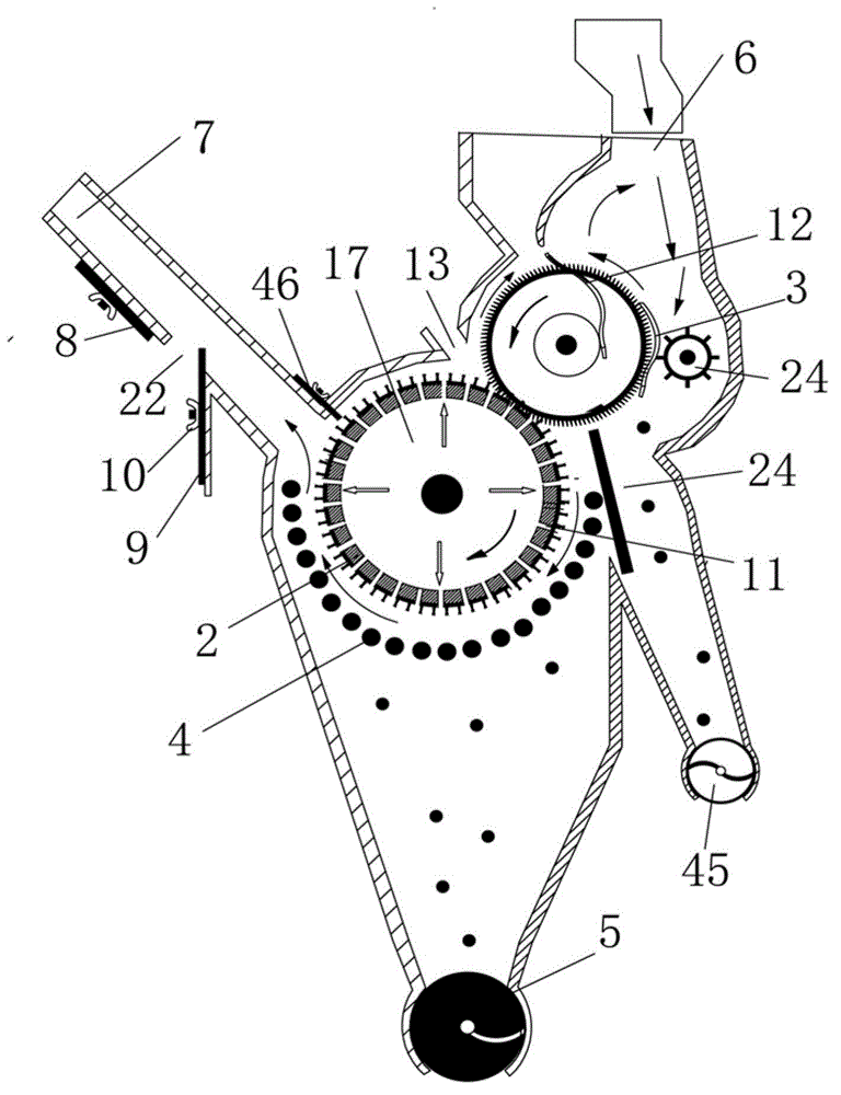
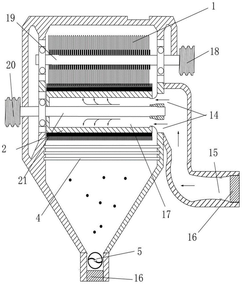
[0039] figure 1 and figure 2 It is a schematic diagram of the structure of the technical solution of the present invention applied to a cotton gin. As shown in the figure, the cotton gin is composed of a shell, a seed cotton input part, a cotton seed and fiber separation part, and a fiber and impurity separation part. The front end of the shell is provided with a working box 6 , the outlet end is the cotton outlet 7, and the shell adopts a closed structure to prevent the seed cotton, impurities, dust and free fibers from overflowing the gin; the seed cotton input part includes the resistance shell rib 3 puller 24; the cotton seed and fiber separation part is separated by a saw blade Roller 1, rib 12, brush roller 2, dripping seed plate 23 and seed row spiral 45 are made up of, and saw blade roller 1 is the saw blade cylinder that the single saw blade and spacer are combined and is assembled on the saw roller shaft 19, and The brush roller is a brush strip fixed on the brush ...
Embodiment 2
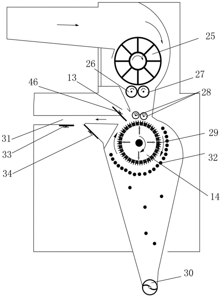
[0046] Embodiment 2 is that the technical scheme of the present invention can be applied to a brush type lint (short-staple) cleaning machine. image 3 It is a structural schematic diagram of a brush type lint (lint) cleaning machine, as shown in the figure, the lint cleaning machine includes a cotton dust cage 25, a cotton stripping roller 26, a cotton pressing roller 27, a cotton feeding roller 28, and a brush roller 29 , the following miscellaneous discharge spiral or miscellaneous suction port 30, cotton outlet 31, miscellaneous discharge grid bar 32, supplementary air regulating plate 33 and pressure regulating plate 34 brush roller windshields 46. Adopt the air induction technical scheme identical with embodiment 1 simultaneously. That is, an air inlet 14 is established at one or both ends of the brush roller 29, and the side has an air inlet 13 of the brush roller 29 and an air outlet 11 between the brush strip or the cotton brushing plate on the brush roller 29 cylinde...
Embodiment 3
[0049] Embodiment 3 is to apply the technical scheme of the present invention to the hairbrush type stripping machine, Figure 4 It is a structural schematic diagram of the cashmere stripping machine. As shown in the figure, the cashmere stripping machine includes a working box 35 seed rollers 36 stripping cashmere ribs 37, saw blade rollers 38, brush rollers 39, miscellaneous grids 40, lower row Miscellaneous spiral or miscellaneous suction mouth 44, linter outlet 41, pressure regulating plate 43 supplementary wind regulating plate 42. Simultaneously adopt the same air induction technical scheme as in Embodiment 1, that is, set the air inlet 14 at one or both ends of the brush roller 39, the brush roller 39 is close to the forward air inlet 13 at the saw blade roller 38, and the brush roller 39 cylinder wall The air outlet 11 between the upper brush strips is provided with an air inlet 15 at one or both ends of the shell wallboard, and the outlet pipe on the other side is pro...
PUM
| Property | Measurement | Unit |
|---|---|---|
| Diameter | aaaaa | aaaaa |
Abstract
Description
Claims
Application Information
 - R&D
- Intellectual Property
- Life Sciences
- Materials
- Tech Scout
- Unparalleled Data Quality
- Higher Quality Content
- 60% Fewer Hallucinations
Browse by: Latest US Patents, China's latest patents, Technical Efficacy Thesaurus, Application Domain, Technology Topic, Popular Technical Reports.
© 2025 PatSnap. All rights reserved.Legal|Privacy policy|Modern Slavery Act Transparency Statement|Sitemap|About US| Contact US: help@patsnap.com