
Cutoff and drainage system for permafrost tunnel edge and heading slope and cutting slope and construction method thereof

A technology of intercepting drainage and frozen soil, applied in excavation, infrastructure engineering, construction, etc., can solve problems such as no meltwater drainage channel, failure of surface drainage system, frost heave of retaining structure, etc., to reduce engineering investment and maintenance costs. , The effect of reducing the degree of soil frost heave and structural stability

Active Publication Date: 2013-06-12
CCCC FIRST HIGHWAY CONSULTANTS
View PDF4 Cites 16 Cited by
  • Summary
  • Abstract
  • Description
  • Claims
  • Application Information

AI Technical Summary

Problems solved by technology

These two drainage systems are mainly suitable for the drainage of filled subgrades, but there are the following problems for the side slopes of tunnels (cuttings): the former uses retaining walls to treat surface water, while underground meltwater is simply intercepted by waterproof boards. Provide drainage channels for meltwater. Groundwater tends to accumulate under the water-retaining walls. In the end of warm season and the beginning of cold season, frost heaving is likely to occur, causing surface uplift. Underground meltwater will seep between the slope and the retaining structure, causing Frost heave problems occur in protective structures; the latter takes into account the discharge of underground meltwater, but after several freeze-thaw cycles, surface drainage ditches will be damaged to varying degrees no matter whether they are prefabricated ditches or masonry masonry ditches. Surface drainage system failure

Method used


Image

  • Cutoff and drainage system for permafrost tunnel edge and heading slope and cutting slope and construction method thereof

Examples


Embodiment Construction

[0031] The present invention will be described in detail below in combination with specific embodiments.

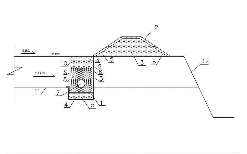
[0032] The cut-off and drainage system of the side slope and the cutting side slope of the tunnel entrance section according to the present invention is provided with a groove 1 located at the top of the side slope 12, the groove width of the groove 1 is 1.2m, and the upper limit of the permafrost depth is 11m. 0.6m below. The bottom of the trench 1 is the thermal insulation and water seepage dark ditch 4, and the original foundation pit soil is backfilled in the thermal insulation and water seepage dark ditch 4; a water-resisting layer is laid on the top of the original foundation pit soil and the side wall of the trench 1 near the side slope; the remaining space of the trench 1 The graded gravel 8 wrapped by the non-woven geotextile 9 is set, and the double-wall corrugated pipe 7 is arranged at the position of the upper limit 11 of the permafrost in the graded gravel 8;...


PUM


Abstract

The invention relates to a cutoff and drainage system for a permafrost tunnel edge and heading slope and a cutting slope and a construction method thereof. The most important work in the engineering construction of the permafrost area edge and heading slope is the prevention of freezing and thawing, a water retaining bank is used for treating surface water, the underground thawing water is drained through a heat-insulation blind ditch, and is simply cut off by a water preventing plate, and a longitudinal drainage channel is not provided for the thawing water. The cutoff and drainage system is provided with a trench, wherein the trench is positioned at the top of the edge and heading slope, the bottom of the trench is provided with a heat-insulation water seepage blind ditch, the original foundation pit soil is backfilled into the heat-insulation water seepage blind ditch, water separating layers are paved above the original foundation pit soil and on the side wall, near the edge and heading slope, of the trench, graded crushed stones which are integrally coated with a non-woven geotextile are arranged in the remained space of the trench, and cohesive soil is backfilled above the graded crushed stones. The cutoff and drainage system has the advantages that the water retaining bank is combined with the heat-insulation water seepage blind ditch to fully treat the surface water and the underground thawing water; the structure type is simple and reliable, and the drainage performance is good; the long-time servicing performance is good, and the curing cost is reduced; and the practicality, the endurance and the little maintenance are realized.

Description

technical field [0001] The invention belongs to the technical field of highway tunnel and subgrade engineering, and in particular relates to a permafrost tunnel side elevation and cutting side slope cutting and drainage system and a construction method thereof. Background technique [0002] The global permafrost area accounts for 25% of the land area. With the continuous development of engineering construction in permafrost areas, permafrost and human economic activities are becoming more and more closely connected, and more and more highway projects are being built in permafrost areas. After the excavation of the side slope or road cutting of the tunnel entrance in the permafrost area, the side slope is exposed, which changes the original water and heat balance of the permafrost. The confluence of the surface will lead to thermal melting and slumping of the slope; surface water or thermal melting water will converge to the foot of the side wall, which will soften and desta...

Claims


Application Information

Patent Timeline
IPC IPC(8): E02D19/20E02D17/20
Inventor 韩常领夏才初王掌军纳启财陆蒙史彦文
Owner CCCC FIRST HIGHWAY CONSULTANTS
Learn More