Magneto-rheological clutch, brake and variable speed control drive assembly device

A magneto-rheological and magnetorheological fluid technology, which is applied to fluid transmission devices, transmission devices, fluid clutches, etc., can solve problems such as optimization combination of difficult-to-separate devices, low degree of automation control, difficult product technology upgrades, etc., to achieve control Social production costs, solving automation functions, and solving the effects of various varieties

Active Publication Date: 2013-06-12
山东格新精工有限公司
View PDF6 Cites 12 Cited by
  • Summary
  • Abstract
  • Description
  • Claims
  • Application Information

AI Technical Summary

Problems solved by technology

[0004] The traditional power transmission, load drive and mechanism control basically adopt the form of separate installation to configure the relevant mechanical devices. The design distribution of the clutch, brake and speed change transmission devices required for the transmission process is relatively scattered, and the types of parts involved are very complicated. , the degree of automatic control of the device is very low. Therefore, compared with the present invention, the structural parts of the traditional product are large in size, the number of parts is large, and the production cost is high. Moreover, it is difficult for the traditional design technology to perform the functions of the sorting device. Optimize the combination, it is more difficult to support the technical upgrade of the mechatronics of the product
At present, no precedent has been found to integrate the above-mentioned sorting device into a power transmission assembly device and apply magnetorheological control technology to control and manage the power transmission function process

Method used


Image

  • Magneto-rheological clutch, brake and variable speed control drive assembly device
  • Magneto-rheological clutch, brake and variable speed control drive assembly device
  • Magneto-rheological clutch, brake and variable speed control drive assembly device

Examples


Embodiment

[0034] The invention innovatively integrates the three functional mechanisms of the clutch, brake and transmission into a drive box assembly component unit, and takes the lead in applying magnetorheological technology to the field of power control of small and medium-sized vehicles, and solves the problem of using magnetorheological fluid As a power transmission medium, it realizes the operation, control and management of the clutch, brake and speed change of the vehicle power.

[0035] 1. Process procedure

[0036] 1. First prepare the parts and magnetorheological fluid materials produced according to the attached drawings.

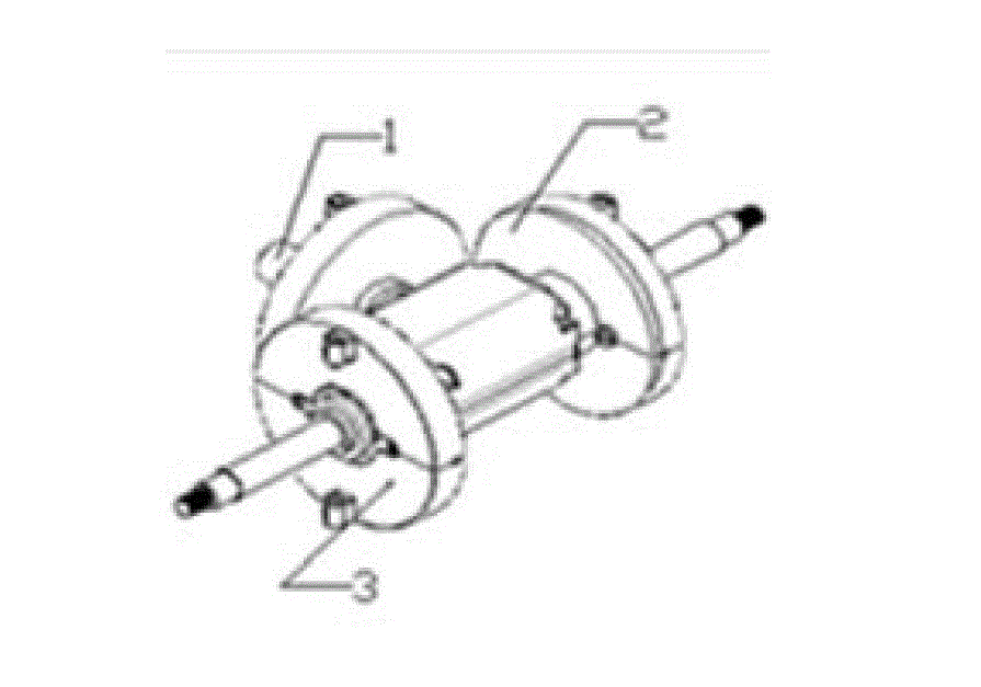
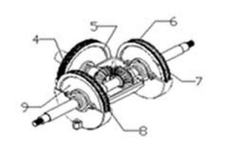
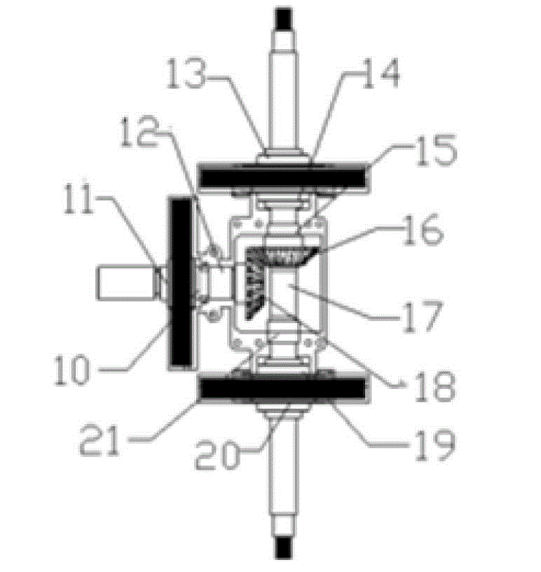
[0037]Specifically, it includes a shaft coupling 1, an upper housing 2, a lower housing 3, a clutch coil 4, a clutch housing 5, a brake coil, a brake housing, a clutch frame shaft 10, a clutch disc shaft 11, a clutch bearing 12, Brake disc frame, reversing bearing, reversing gear 16, reversing shaft 17 and power gear 18, described shaft coupling 1, clut...


PUM


Abstract

The invention belongs to the technical field of drive assembly devices, in particular to a magneto-rheological clutch, brake and variable speed control drive assembly device, which is formed by assembling a coupling, an upper shell, a lower shell, a clutch coil, a clutch shell, a brake coil, a brake shell, a clutch holder shaft, a clutch disc shaft, a clutch bearing, a brake pad bracket, a reversing bearing, a reversing gear, a reversing shaft and a power gear; when a vehicle starts, the coupling inputs power to the clutch disc shaft; when the vehicle runs, current is input into the clutch coil, a magneto-rheological material is subjected to phase change, and the power is transmitted to the reversing shaft from the clutch disc shaft through the power gear and the reversing gear; and when the vehicle is braked, the current input into the clutch coil and the brake coil is cut off, the magneto-rheological material is subjected to phase change, and the brake pad bracket and the reversing shaft are in a brake locking state. The device solves technical problems to achieve light-weight product, simple structure, material reduction and intelligent control, and powerful support is provided for promoting new materials, new technologies, new processes and technical upgrade of products.

Description

[technical field] [0001] The invention relates to the technical field of transmission assembly devices, in particular to a transmission assembly device controlled by a magneto-rheological clutch, a brake, and a transmission, and a transmission method and application thereof, which are suitable for small and medium-sized electric vehicles, engineering logistics vehicles, and agricultural vehicles , Lifting and handling vehicles, marine driving devices, mechanical power devices and other necessary supporting ranges of use. [Background technique] [0002] Magneto-rheological fluid is a new type of phase-change material. It is a magnetic particle suspension mixed with high magnetic permeability and low hysteresis (micron or even nanoscale) soft magnetic particles and non-magnetic liquid. When there is no magnetic field, the suspended particulate iron particles move freely with the liquid; when a magnetic field is applied, these suspended particulate iron particles are attracted ...

Claims


Application Information

Patent Timeline
Patent Type & Authority Applications(China)
IPC IPC(8): F16H47/00F16D57/00F16D37/00
Inventor 沈锡鹤劳渝声魏民
Owner 山东格新精工有限公司
Why Eureka
Try Eureka