Steam calcining furnace under pressure

A calciner and steam technology, applied in the direction of drying solid materials, non-progressive dryers, dryers, etc., can solve the problem of inability to ensure removal of crystal water and free water, unfavorable separation and discharge of finished materials, and failure to meet the needs of large-scale production and other problems to achieve uniform heating, reduce material loss, and reduce waste

Active Publication Date: 2013-06-12
CHENGDU TIANBAO HEAVY IND
View PDF5 Cites 2 Cited by
  • Summary
  • Abstract
  • Description
  • Claims
  • Application Information

AI Technical Summary

Problems solved by technology

The furnace body of the traditional steam calciner cannot withstand the pressure required by the process, and cannot guarantee that the material will remove crystal water and free water under a certain temperature and pressure. The dehydration efficiency is low, and the finished materials produced are not conducive to separation and discharge, and cannot meet industrialization Large production needs
[0003] In the process of feeding and discharging the traditional structure of the calciner, under the action of the pressure in the furnace, it is easy to have difficulty in feeding and discharging the material or the situation that the material cannot be fed in and out, and it is also not conducive to the discharge of the furnace gas.

Method used


Image

  • Steam calcining furnace under pressure
  • Steam calcining furnace under pressure
  • Steam calcining furnace under pressure

Examples


Embodiment

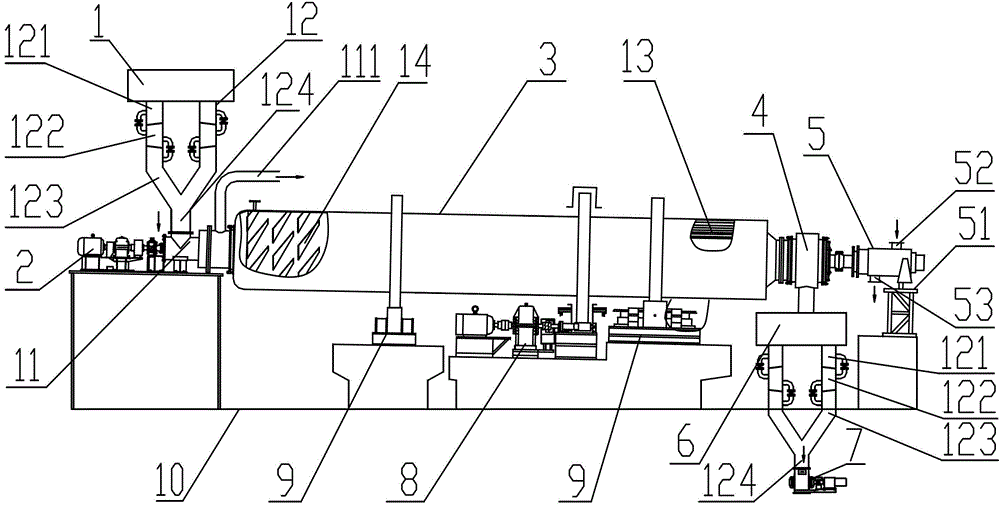
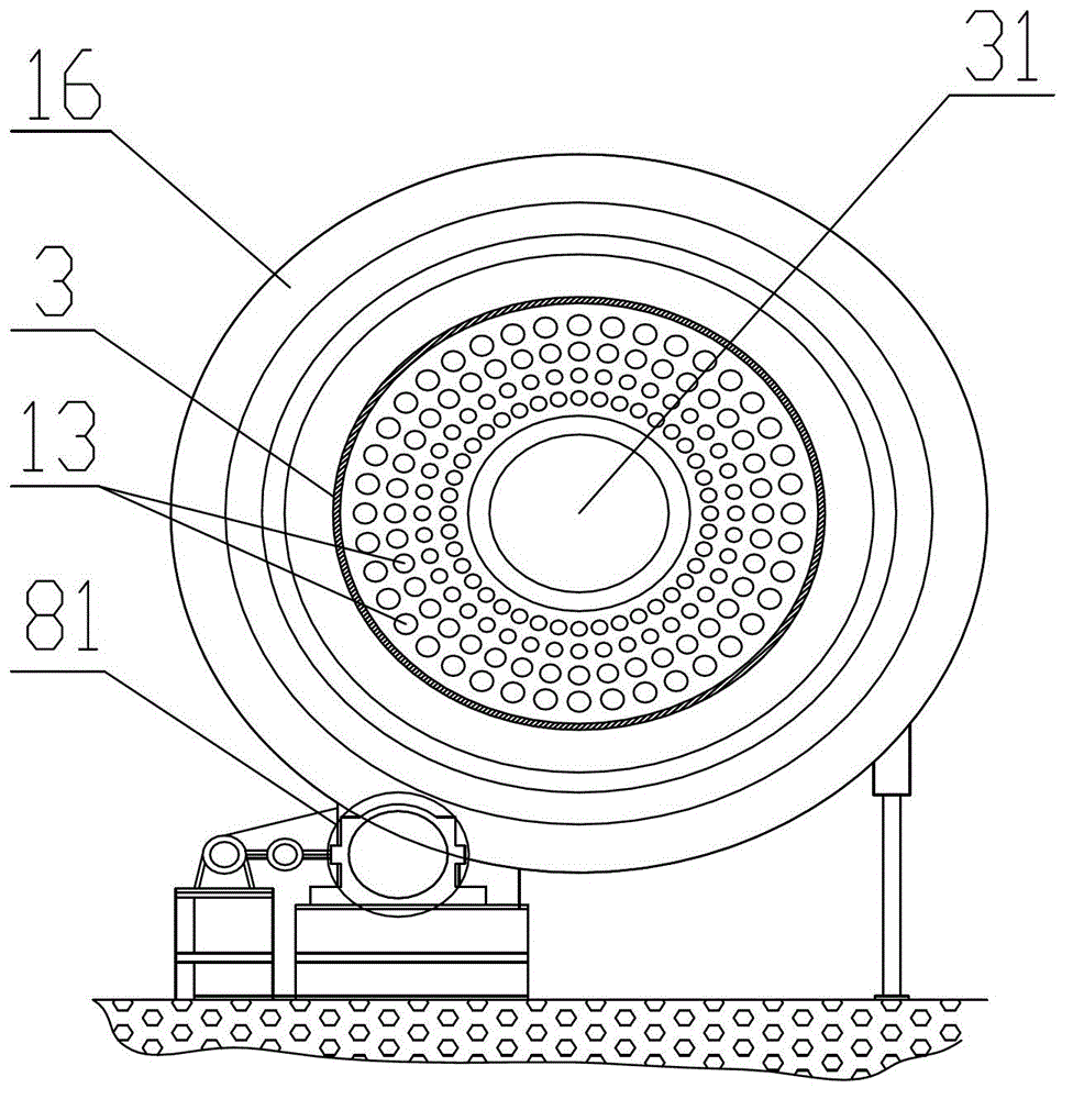
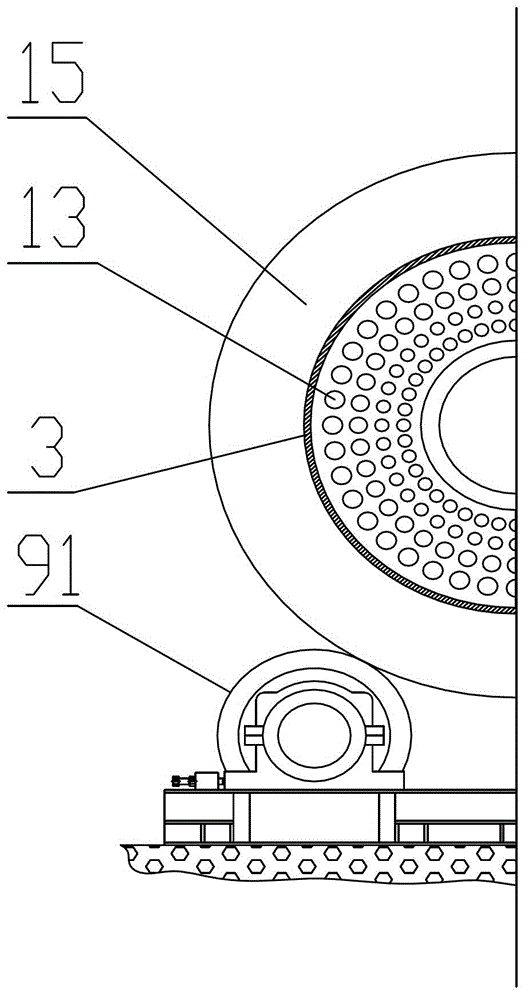
[0031] Such as Figure 1 ~ Figure 6 As shown, a pressurized steam calciner is mainly composed of a raw material bin 1, a feed bin 11, a furnace body 3 and a steam inlet shaft 5. The furnace body 3 has a reaction chamber 31, a feed bin 11 and a furnace body 3. The front end is connected, and a transmission device 8 is provided outside the furnace body 3, and the raw material warehouse 1 and the feeding warehouse 11 are connected through a three-stage feeding device 12. The front end of the furnace body 3 is an air outlet chamber, and a furnace gas outlet 111 is provided on the air outlet chamber. The steam inlet shaft 5 communicates with the rear end of the furnace body 3. The steam inlet shaft 5 has an inlet steam passage communicating with the reaction chamber 31 of the furnace body 3, and a steam inlet 52 is provided on the steam inlet shaft 5. An intermediate warehouse 4 is also provided between 5 and the furnace body 3, and a finished product warehouse 6 is connected to th...


PUM


Abstract

The invention discloses a steam calcining furnace under pressure, which mainly consists of a raw material cabin, a feeding cabin, a furnace body and a steam inlet shaft, wherein a reaction cavity is arranged inside the furnace body, the feeding cavity is communicated with the front end of the furnace body, a transmission device is arranged outside the furnace body, the raw material cabin and the feeding cabin are communicated through a three-stage material conveying device, the front end of the furnace body is a gas outlet cavity, a furnace gas outlet is arranged on the gas outlet cavity, the steam inlet shaft is communicated with the back end of the furnace body, a steam inlet is arranged on the steam inlet shaft, a middle cabin is also arranged between the steam inlet shaft and the furnace body, a finished product cabin is communicated on the middle cabin, a heating pipe is arranged in a reaction cavity of the furnace body, and a pipeline opening of the heating pipe is communicated with the steam inlet passage of the steam inlet shaft. The steam calcining furnace under pressure realizes the continuous dewatering or production of materials, the material loss is reduced, the work environment of the production site is improved, and the pollution is reduced. In addition, the generated furnace gas can also be recovered and utilized, the resource waste is reduced, and further energy-saving and environment-protection effects are realized.

Description

Technical field [0001] The invention relates to a steam calciner, in particular to a pressurized steam calciner. Background technique [0002] The steam calciner is an important equipment for the production of building materials. Its specific function is to achieve the purpose of dehydration (including dehydrated water and free water) under a certain pressure through heat exchange between steam and materials. The steam calciner of the traditional structure is composed of a feed port, a furnace head part, a furnace body part, a steam inlet shaft and a transmission device. High temperature steam is introduced into the furnace body through the steam inlet shaft, so that the furnace head, The materials in the furnace body are heated or reacted to achieve the purpose of heating decomposition and dehydration. Then, the dehydrated product is discharged through the furnace head, and the transmission device plays the role of driving the furnace body to rotate. The furnace body of the tra...

Claims


Application Information

Patent Timeline
Patent Type & Authority Applications(China)
IPC IPC(8): F26B11/04F26B25/00F26B25/02
Inventor 邓亲华张志广钟玉华张旭亮刘芳兵
Owner CHENGDU TIANBAO HEAVY IND
Why Eureka
Try Eureka