Optical fiber distributed disturbance sensor positioning method

A technology of optical fiber distribution and positioning method, which is applied in the direction of mitigating unwanted effects, and can solve problems such as complex algorithms, low precision, and large amount of calculation, and achieve the effect of simplifying the calculation process and precise positioning

Inactive Publication Date: 2013-06-12
BEIJING JIAOTONG UNIV
View PDF3 Cites 5 Cited by
  • Summary
  • Abstract
  • Description
  • Claims
  • Application Information

AI Technical Summary

Problems solved by technology

[0012] However, the existing positioning method based on the cross-correlation function cannot be applied to the case of low signal-to-noise ratio, and the positioning accuracy is low when the external conditions are not good (such as slow phase change, polarization fading, and scattering noise).
[0013] In addition, there are various time-delay estimation algorithms in the existing technology (such as generalized correlation method, phase spectrum method, parameter model time-delay estimation, etc.), but the calculation load is large and the algorithm is complicated. In the optical fiber distributed disturbance sensor application, the accuracy is low, and the current lack of practicality

Method used


Image

  • Optical fiber distributed disturbance sensor positioning method
  • Optical fiber distributed disturbance sensor positioning method
  • Optical fiber distributed disturbance sensor positioning method

Examples


Embodiment 1

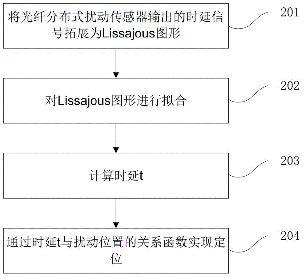
[0032] figure 2 A flow chart of a positioning method for an optical fiber distributed disturbance sensor provided in Embodiment 1 of the present invention, as shown in figure 2 As shown, it mainly includes the following steps:

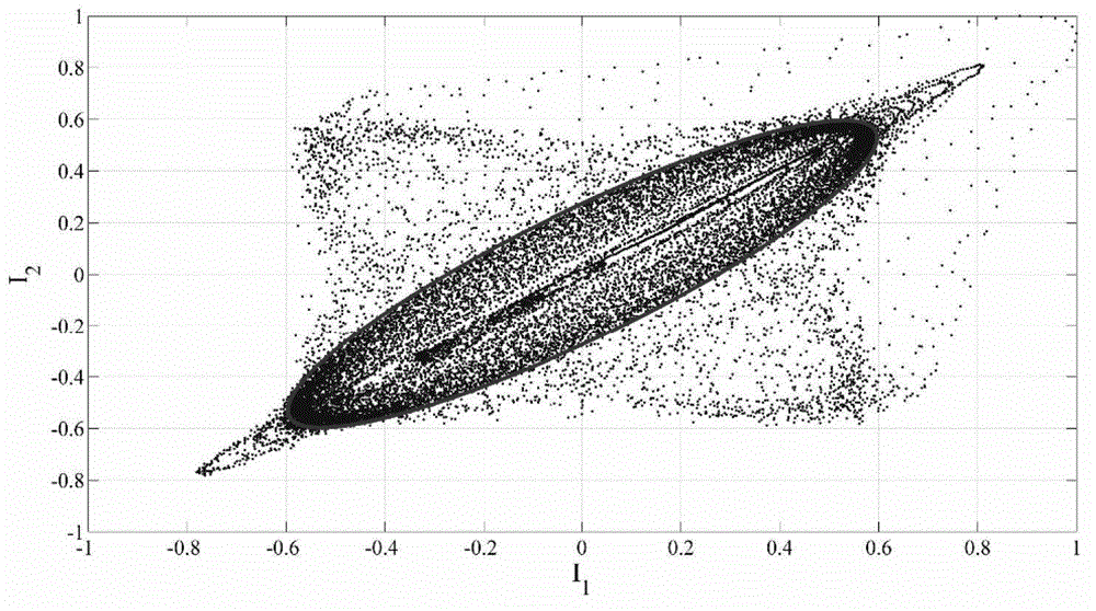
[0033] Step 201, expand the time-delay signal output by the optical fiber distributed disturbance sensor into a Lissajous graph.

[0034] First, obtain the time-delay signal I output by the fiber optic distributed disturbance sensor 1 (t) with I 2 (t); Then, the two signals are sampled according to the preset sampling frequency (for example, the sampling frequency is set to f s =2MHz) and sampling period (sampling period T s =1 / f s ) normalized to a frequency map; finally, according to the obtained I from the frequency map 1 (t) with I 2 (t) the frequency ratio plotted with I 1 (t) is the abscissa with I 2 (t) is the Lissajous (Lissajous) graph arranged in the form of points on the ordinate, and each time-delay signal in this graph is arrang...


PUM


Abstract

The invention discloses an optical fiber distributed disturbance sensor positioning method, which comprises the following steps of: expanding time delay signals I1 (t) and I2 (t) output by an optical fiber distributed disturbance sensor in a Lissajous pattern arranged in a point mode; fitting an ellipse with semi-major axis length a and semi-minor axis length value b by taking coordinates (x, y) in the Lissajous pattern as a central point and azimuth angle as alpha; and if the ratio c of the number of the points in the ellipse to the total number exceeds a threshold value p, performing linear fitting by using the semi-minor axis length value b to calculate time delay t, and realizing positioning through the relation function of the time delay t and the disturbance position. According to the method provided by the invention, the positioning accuracy is improved, and the amount of calculation is reduced.

Description

technical field [0001] The invention relates to the technical field of optical fiber distributed disturbance sensors, in particular to a positioning method for optical fiber distributed disturbance sensors. Background technique [0002] The optical fiber distributed disturbance sensor can detect and locate the disturbance at any point on the sensing fiber. With its important technical advantages such as long monitoring distance, positioning, and no need for external power supply, it can be widely used in perimeter security, oil and gas pipeline early warning, communication, etc. Line monitoring as well as large structure monitoring. [0003] Among the various implementation schemes of fiber optic distributed disturbance sensors, the scheme based on M-Z (Mach-Zehnder, Mach-Zehnder) interferometer has the advantages of simple structure, high positioning accuracy, high sensitivity, wide sensitive vibration spectrum, and no need for phase demodulation. It has become the mainstr...

Claims


Application Information

Patent Timeline
Patent Type & Authority Applications(China)
IPC IPC(8): G01D3/028
Inventor 梁生盛新志娄淑琴陈京惠王思远吴重庆王智王健刘岚岚李政勇张丽梅
Owner BEIJING JIAOTONG UNIV
Why Eureka
Try Eureka